Eng-Tips is the largest engineering community on the Internet

Intelligent Work Forums for Engineering Professionals

  • Congratulations waross on being selected by the Tek-Tips community for having the most helpful posts in the forums last week. Way to Go!

question about small submersible pump bhp vs current characteristics 5

Status
Not open for further replies.

electricpete

Electrical
May 4, 2001
16,774
0
0
US
I have a question about Goulds WE0511HH pumps that we use in a sump application: Submersible Pump. 1/2 HP, 115 Volt, 60 Hz, 3.87″ Impeller, 2″ NPT Discharge, 20′ Cord, 3/4″ Solids.

I'm not sure where is the best place to find info on this pump (google floods me with distributors), but here is a link

Question 1: what does the bhp vs flow curve look like? Does bhp increase with flow, or decrease with flow, or increase then decrease with a peak near bep in the middle?

Question 2 (if question 1 is unknown / ambiguous): what is the construction of the pump (axial flow, radial flow, number of stages)?
I think it's radial flow single stage. I’m under the impression single stage radial flow pumps generally have increasing bhp vs flow while single stage axial flow pumps generally have decreasing bhp vs flow.

Background: We have some chronic problems with this pump tripping, often on start, sometimes during run. Historically we have focused a lot on filtering the suction and blamed the trips on debris. We just noticed we have Bussman KTK-15 fast act fuse which we’ll be upgrading to KTK-20 in hopes to solve the problem. Beyond that we’d still like to understand what role is the system operating point (flow resistance) and also the impact of debris that might end up obstructing flow (we immediately neck the 2” discharge of the pump down to ¾” pipe). Obviously if debris jams the pump that would cause trip but I'm just interested in the effect of the operating point on the current. There are other people here involved reviewing other aspectsm but my piece is just the question about effects of operating point effects on current.


=====================================
(2B)+(2B)' ?
 
Replies continue below

Recommended for you

The missing info in your calculation is efficiency. Tends to be low at low and big flows so power tends to steadily climb as flow increases or doesn't drop off.

Do you actually know what the normal running flow rate is?

Remember - More details = better answers
Also: If you get a response it's polite to respond to it.
 
One thing to consider is that submersible pumps motors are usually rated to run at higher current for their rated output due to being product cooled, unlike a none submerged motor running in air.

It is a capital mistake to theorise before one has data. Insensibly one begins to twist facts to suit theories, instead of theories to suit facts. (Sherlock Holmes - A Scandal in Bohemia.)
 
bimr - so would you classify it as radial flow, axial flow, or mixed?

LittleInch - Yes, I have one value of pump efficiency but no curve, so limited ability to forecast the shape of BHP curve from FHP curve. I think you're saying that if pump efficiency curve was taken into account, it would be a monotonically increasing curve of BHP vs flow? What makes you say that?

We don't have a flow indicator, but I'll check around to see if there is a way to begin to estimate actual flow rate in our system. As I mentioned we have an immediate neckdown in piping from the 2" discharge pipe to a 3/4" pipe which looks very odd, but I don't know how long that 3/4" pipe runs for.

Artisi - I have seen some motors (noteably TEAO) where the hp rating of the motor takes credit for the favorable environmental conditions (flow over the motor in the case of TEAO, plays a similar role as submergence I would think) and is stated as such on the nameplate. I don't have any nameplate photo for this motor, so at first glance I'm leery of taking credit for some rating beyond 0.5hp (although as Ed points out probably none of this is very exact anyway)


=====================================
(2B)+(2B)' ?
 
electricpete said:
bimr - so would you classify it as radial flow, axial flow, or mixed?

No, not a radial flow pump. In a radial flow pump, the liquid enters at the center of the impeller and is directed out along the impeller blades in a direction at right angles to the pump shaft.

radial25_wy8ila.gif


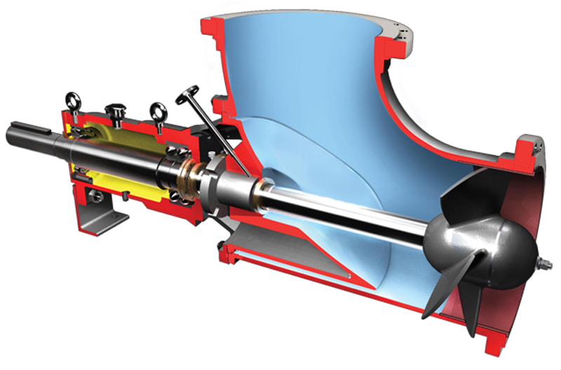
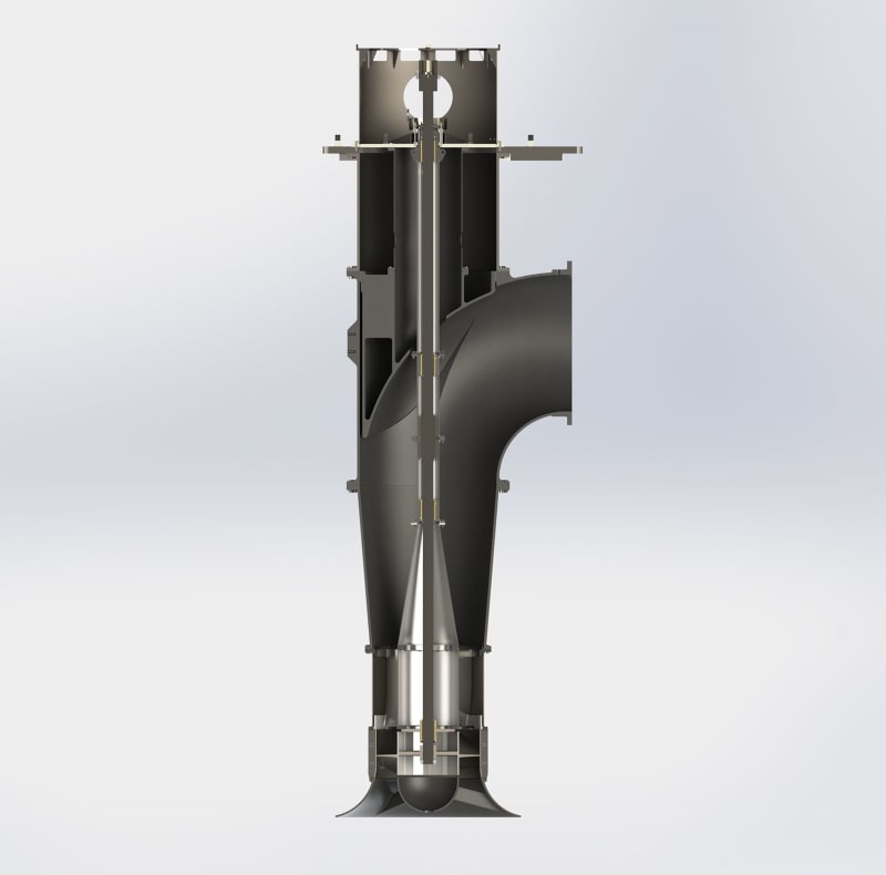
No, not an axial flow pump. Axial flow pumps are of the propeller type, in which the rotation of the impeller forces the water forward axially, and do not strictly qualify as centrifugal pumps. Mixed flow pumps act partly by centrifugal action and partly by propeller action, the blades of the impeller being given some degree of ‘twist’.

R_vpmztc.jpg


No, not a mixed flow pump. A mixed flow pump is a centrifugal pump with a mixed flow impeller.

axial-mixed-flow-FRONT-SECTIONAL_gbemv2.jpg


The submersible pump you are referencing is called a vortex pump.

showfou-sv-pumps-sketch_o34tjd.png


Submersible Vortex Pump

Goulds Vortex Pump
 
While I kinda concur with something wrapped around the shaft OR the bearings have failed think about this:
If the start cap is bad it would act exactly the same as you're seeing. It would have a hard time starting and suck-down LRA until it managed to trip the small single phase motor built-in overload. Then try again and maybe manage to get up to a faster speed before tripping-out. Then on a third cycle get running fast enough to run normally as it's now finally actually fully started.

Does it have a start capacitor?

Keith Cress
kcress -
 
Thanks that's some great info all around. As luck luck would have it, we have recorded 9 more starts on Thursday 5/19. They were not particularly prudent starts (many quick starts in a row resulting in trips, lots of abuse of that motor) but that's what was done.

I continued the numbering of starts from 1/2/3 on 5/18 to 4 through 12 on 5/19 (the starts numbered 4 thru 12 are shown attached). It is an interesting opportunity to look at these starts some more, even though maybe the resulting troubleshooting actions are already obvious straightforward.

On 5/19 I saw some normal starts similar to the start 3 (example start 4 on slide 2). I saw some struggling starts with oscillation and then trip similar to start 1 (example start 6 on slide 3). Now here are two new types of starts I saw:

Start 12 (slides 13 and 14) - 5 seconds oscillating near locked rotor current. During this 5 sec the spikes get further apart. After 5 seconds the current drops to normal and the motor continues to run. So it struggled and then finally succeeded.

Start 8. Steady locked rotor current for 4.5 seconds (no oscillation), and then trip. The trip after only 4.5 seconds (where other starts lasted 9+ seconds before trip) I attribute to recent previous frequent starts with insufficient rest/cooling between starts...

To me the steady current in start 8 seems more consistent with completeley locked rotor and something like a cap problem. Myself I typically associate motor starting cap problem with complete inability to start where the motor never moves at all (like I think was going on in start 8). Typically on other motors I've seen with starting cap problem if you give it a push to get started, then it continues to start successfully, at least in the motors I have played with. I guess the starting capacitors play different roles in different styles of motors, so maybe starting cap problem could contribute to a weak start rotating start in some of those? I'm not sure. Certainly a voltage problem could cause a weak rotating start.

I wasn't present during all of this. I wish I was. The technicians who did the test said they could in general tell when water was flowing but they weren't really paying attention to whether water was flowing or not during all of these starts. (They never noticed a start with water not flowing but they couldn't guarantee water flowed during all start attempts)

At any rate, I don't rule out we might have multiple problems and one of them could be starting cap or voltage problem, so I definitely have enough ammunition to suggest checking those things (along with inspecting the pump, which hasn't been done yet).

=====================================
(2B)+(2B)' ?
 
 https://files.engineering.com/getfile.aspx?folder=7ef24e56-7184-4e2f-bde4-4998f99527c0&file=May19.pdf
I'm amazed at how much time we have taken discussing a 1/2 hp submersible pump....

It's not a vortex pump, but has some strange characteristics - more like an axial pump in that the difference in head from no flow to max flow is about 10:1. This is worse for the High Head HH versions of the pump.

So it makes it difficult to know what the power does as flow changes. It might peak at some point and then reduce or go in a wave form.

But from the last post it looks like this unit doesn't like starting. Why? Could be a motor start issue, could be stuff wrapped around the impellor, could be just a poor construction. It does seem that the starts in some cases jump a bit at a time, but just does't start.

So time to pull the unit and take it apart I think....


Remember - More details = better answers
Also: If you get a response it's polite to respond to it.
 
> I'm amazed at how much time we have taken discussing a 1/2 hp submersible pump....

Haha yes it is quite a bit, isn't it. I can blame part of that on some organizational factors (limited manpower for troubleshooting at the moment, among other things). We also want to make sure we not only fix the problem but understand it well enough to make a dent in what we now perceive as a chronic problem. And the solutions may not be as simple to implement as you'd think: for one thing we have an onerous configuration control process for changes that are not "like-for-like". For another thing, this is actually a sump sample pump which feeds a monitor for certain sump contaminants (I simplified when I initially called it a sump pump). The relevance of that fact is that I am not sure whether changing the flow rate would change the calibration of the monitor (I'll have to look into that further to see how the monitor works).

But I'll have to take some of the blame myself. For one thing I have a wandering personal style where writing everything down helps me to organize my thoughts.... and so why not just write it all down here on the forum!?! (half kidding, but that explains to some extent the wandering thread).

As if that's not bad enough for you readers, I have ended up with multiple purposes in this single thread:
[ol 1]
[li]To understand what specifically caused these particular trips[/li]
[li]To understand what might lead to trips in the future if we don't change anything beyond swapping out the pump/motor like for like[/li]
[li]To understand the original question BHP vs flow. After I made a statement to a manager that the bhp is not necessarily monotonically increasing with flow, he turned around and assigned me an action to figure out what the curve looks like for this particular pump. Being cognizant of technical factors and also political factors, I feel a burden to complete my assigned action the best that I can. [/li]
[/ol]

On the last question, here is a cutaway from the manual
SumpPumpCrossSection_awwfpa.gif


I see it looks like the flow enters the bottom and exits purely radially. Is that enough to call it a radial flow pump?

(btw the annotations I put on the cutaway drawing are just to highlight to myself that it's an oil-filled motor and the cap is located inside the oil)

I may try to engage the OEM with some questions at some point if I can find a good person to talk to.

Thanks again for all your help and patience (with my rambling)


=====================================
(2B)+(2B)' ?
 
I suspect the only way to get a good BHP vs flow is to do aa set of tests yourself.

So /you would need to have a control valve and a flow meter with pressure guage up stream and then screw the valve down closed, get the pump running and then then do a series of increasing flow in say 5 GPM steps and measure the power in.

Yes I think it's a radial type pump, but I suspect with some straight or straight angled blades and as said, the pump curves resemble more of an axial flow pump than a normal centrifugal, but then its a small sump pump.

We don't know what caused the trips and I doubt you'll ever find out unless you either replace the capacitor or take the pump apart and confirm or deny that there's some sh1t stuck in it. These things are as simple as you can get. If the motor doesn't start, 1st point of call is to check the motor. There should be enough torque to get the pump moving unless you've got a rock stuck in it or something else is clogging the impellor or shaft.


Remember - More details = better answers
Also: If you get a response it's polite to respond to it.
 
The manufacturers call these submersibles vortex pumps. You can call these pumps anything you want, but if you look at the cross-sections above, you can see that the pump in question is not constructed like a radial pump.

A radial pump has:

1. Flow passing through the middle of the impeller;
2. Has an impeller instead of open ended vanes;
3. Doesn't have a larger open end than a vortex pump;
4. A radial pump is not considered to be non-clogging unless the pump is very large;
5. A radial pump has a higher pumping efficiency than a vortex pump.

An axial pump has a propeller instead of a vane.

The vortex pump is a type of vane pump. In terms of principle and structure, it is different from centrifugal and axial flow pumps. Because it sucks and discharges liquid by the action of swirling liquid generated by impeller's high-speed rotation, it is called a vortex pump. That is why the vortex pump is considered to be non-clogging (or seldom clogging) and also has a lower pumping efficiency.

Link

I do agree with LittleInch that you are spending too much time on this as these pumps are inexpensive and considered to be throw-aways. Many of these sump pumps are configured with cheap level switches that last only 5-7 years. You can get around the level switch issues by hot wiring the pump and using an electronic switch like the levelguard.

 
Thanks bimr. I can see the idea of vortex pump like in your original figure can move chunky fluid without anything having to go through the impeller, in part I guess due to the open vane design of the impeller and in part due to the fact the impeller is above the elevation of the discharge. Our pump in the figure I excerpted above is slightly different than the one you posted in that our impeller (piece 1) is at the same elevation as the discharge. Does that change your classification at all? (just a curiosity).

> I do agree with LittleInch that you are spending too much time on this as these pumps are inexpensive and considered to be throw-aways

I have addressed some of the challenges described in my last message. (Or you could just say I have some issues...)

I've recommended:
[ol 1]
[li]Replace pump/motor. Inspect sump and accessible portions of pump that can be seen through the suction port. Clean sump.[/li]
[li]Perform additional monitored starts of replacement pump/motor, this time monitoring voltage near motor along with current (and give it some rest between starts).[/li]
[li]For removed pump/motor, hold onto it and we'll review how difficult it would be to disassemble that oil-filled unit for further checks of impeller and capacitor.[/li]
[/ol]

====================================
(2B)+(2B)' ?
 
Have you been able to get in touch with Goulds to get an engineering submittal or anything on this pump? When I deal with them on a project I usually get a lot more documentation than is available on the website or third party downloads. I'd hate to see you spend a good deal more time chasing down the BHP curve through testing only to have it readily available from the manufacturer.
 
No I haven't tried the OEM yet. Do you have any contacts in mind? Or just start with the main number.

=====================================
(2B)+(2B)' ?
 
I've got a contact I can chase down that might be able to get back to me within the month. Xylem brands have been having issues even picking up the phone.
 
[link electricpete]Does that change your classification at all? (just a curiosity).[/url]

The reason that your pump model doesn't have a more recessed vane is because the pump is so small.

 
"For removed pump/motor, hold onto it and we'll review how difficult it would be to disassemble that oil-filled unit for further checks of impeller and capacitor."

I'm pretty sure from looking at some manuals and drawings that the inlet plate just unbolts from the rest of the oil filled motor section so that' bit should be easy.

Dismantling the rest looks equally easy to unbolt it, but then you have the rotor and all the insides in a vat of oil.

Rather than all these stop starts to pick up some samples, could you not just keep it running for a set period and route the output back into the tank?

It would be nice to see what sort of impellor or vanes it has and whether there is anything there which is restricting its free movement / increased starting torque. Whatever it has it is pretty basic and needs to just whirl around creating some sort of flow in the liquid.

Let us know how you get on and send some photos of the pump when you've taken the casing off please.


Remember - More details = better answers
Also: If you get a response it's polite to respond to it.
 
Thank Rputvin, that's a few years newer.

As far as the operating point for this motor, we do have a flow indicator in the monitor itself and I'm told the pump typically pumps 5-6gpm (way to the left side of the curve). The monitor calibration is not affected as long as flow remains above 3gpm, at which point we get a low-flow alarm from a flow switch (there is no history of low flow alarms except when the pump has tripped). Being that far left on the curve we have more reason to think that increasing flow would increase current in this region, correct? I don't think decreasing flow will be an option and I don't think increasing flow would help us. If I can figure out a way to increase flow slightly and check current I'll do that.

> Rather than all these stop starts to pick up some samples, could you not just keep it running for a set period and route the output back into the tank?

We mostly operate the pump in manual mode continuous run, so it doesn't see much cycling normally. All the cycles I posted from 5/18 and 5/19 were starts for testing purposes (someone got just a little bit carried away... it wasn't me).

The original design of the monitor provided for automatic cycling of the pump controlled by the monitor (even though it now runs in manual / continually). The motor is switched by a Teledyne 615-6 solid state relay (rated 40A at 60hz) controlled by 24vdc. As an aside the relay has a varistor on it that has an odd bulge in the coating. Even if the varistor is degraded, I don't see any relevance to the motor tripping (if anything it might threaten the electronics). More info attached. Our technicians plan to replace the ssr / varistor out of an abundance of caution when they swap the pump. I don't know much about ssr's... there isn't any degradation mode that would send a low voltage to the motor, is there? (I guess if we had checked voltage before like Keith said, then we'd know that, but as it is we won't get a voltage check until after SSR is replaced).

New pump/motor is in the shop ready for installation, it looks just like the picture in the brochure. I will be able to get a better look at the old one today or tomorrow.

=====================================
(2B)+(2B)' ?
 
 https://files.engineering.com/getfile.aspx?folder=948cfbee-4d16-4fa0-b96e-2e5c2d07df2a&file=SolidStateRelay.pdf
UPDATE - pump was removed and inspected.

[ol 1]
[li]photos of inspection are here.[/li]
[li]The impeller was slightly rough to rotate by hand.[/li]
[li]There was no abnormal foreign material, but...[/li]
[li]the upper and lower bearings were both degraded (lower bearing has around 0.030” clearance and upper bearing has around 0.020” clearance). The impeller rubbed the bottom of the stationary casing (possibly due to the degraded bearing). The motor rotor may have rubbed the stator.[/li]
[li]The friction associated with these conditions may have been the cause of the erratic pump performance.[/li]
[li]The pump/motor had been installed since January 2022[/li]
[li]The drained fluid was only oil, there did not appear to be any water mixed in[/li]
[/ol]

This pump/motor had last been replaced 5 months ago (it was new at that time). It's strange that both bearings degraded. Do you guys think the operating point (6gpm far on the left of the curve) may play a role?

I might have the bearings cut apart for further inspection. Also might try to check the mechanical balance of that impeller.


=====================================
(2B)+(2B)' ?
 
 https://files.engineering.com/getfile.aspx?folder=6785794e-a5fc-4c73-9478-e19570a8a47c&file=RA_SamplePump.pdf
Status
Not open for further replies.
Back
Top