Eng-Tips is the largest engineering community on the Internet

Intelligent Work Forums for Engineering Professionals

  • Congratulations waross on being selected by the Tek-Tips community for having the most helpful posts in the forums last week. Way to Go!

question about small submersible pump bhp vs current characteristics 5

Status
Not open for further replies.

electricpete

Electrical
May 4, 2001
16,774
0
0
US
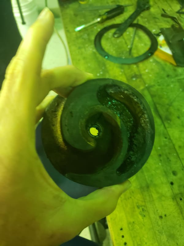
I have a question about Goulds WE0511HH pumps that we use in a sump application: Submersible Pump. 1/2 HP, 115 Volt, 60 Hz, 3.87″ Impeller, 2″ NPT Discharge, 20′ Cord, 3/4″ Solids.

I'm not sure where is the best place to find info on this pump (google floods me with distributors), but here is a link

Question 1: what does the bhp vs flow curve look like? Does bhp increase with flow, or decrease with flow, or increase then decrease with a peak near bep in the middle?

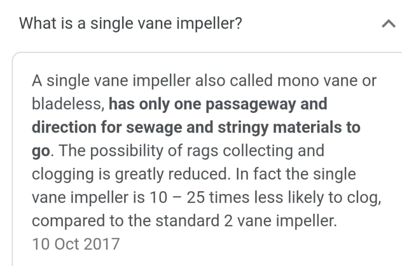
Question 2 (if question 1 is unknown / ambiguous): what is the construction of the pump (axial flow, radial flow, number of stages)?
I think it's radial flow single stage. I’m under the impression single stage radial flow pumps generally have increasing bhp vs flow while single stage axial flow pumps generally have decreasing bhp vs flow.

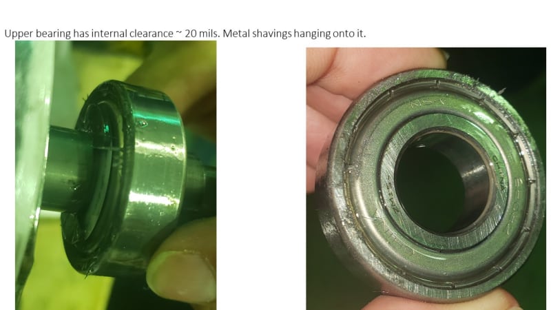
Background: We have some chronic problems with this pump tripping, often on start, sometimes during run. Historically we have focused a lot on filtering the suction and blamed the trips on debris. We just noticed we have Bussman KTK-15 fast act fuse which we’ll be upgrading to KTK-20 in hopes to solve the problem. Beyond that we’d still like to understand what role is the system operating point (flow resistance) and also the impact of debris that might end up obstructing flow (we immediately neck the 2” discharge of the pump down to ¾” pipe). Obviously if debris jams the pump that would cause trip but I'm just interested in the effect of the operating point on the current. There are other people here involved reviewing other aspectsm but my piece is just the question about effects of operating point effects on current.


=====================================
(2B)+(2B)' ?
 
Replies continue below

Recommended for you

Here is another view of the impeller. It rotates at 3500rpm. I'm sure others could explain better than me why it's shaped that way. There is a dead / void space which I think is supposed to help maintain balance (it would be further out of balance if the void space was filled). But gunk accumulates in the void space.

Now that you mention it, I guess this design would cause a hydraulic unbalance force too, but I have no idea how much.

20220601_111058_jqmu3x.jpg


=====================================
(2B)+(2B)' ?
 
I guess I should have mentioned there were metal shavings clinging to the upper bearing as if it was magnetized (slide 8). I can't explain it, so I tend to discount it as irrelevant, but you never know...
UpperBearing_oc2nav.jpg


=====================================
(2B)+(2B)' ?
 
Yes you're probably right that attention was given to mechanical balance in the geometry of that impeller (I think it's cast). I'm not sure if the OEM went the extra step to do a rotating balance check. Thinking about that gunk some more, it's probably roughly the same density as the water it displaces, so maybe not much effect on mechanical unbalance. At any rate, we will be able to check and quantify the mechanical unbalance by putting the rotor and impeller on a balance stand.

But the fluid unbalance (based on lack of angular symmetry of the pumping action) is a different matter. What do you guys think about that... could that be a significant force?

I'm just trying to think of things that may have affected both bearings in such a short time (5 months since install)

Next steps will include inspection of the bearings after they are cut apart (to see if they held onto any clues about their killer!).

=====================================
(2B)+(2B)' ?
 
Nothing unusual with the impeller, it's simply a single channel design, and would be balanced during its manufacture.

It is a capital mistake to theorise before one has data. Insensibly one begins to twist facts to suit theories, instead of theories to suit facts. (Sherlock Holmes - A Scandal in Bohemia.)
 
Screenshot_20220603-121634_Google_uqi8x6.jpg


It is a capital mistake to theorise before one has data. Insensibly one begins to twist facts to suit theories, instead of theories to suit facts. (Sherlock Holmes - A Scandal in Bohemia.)
 
I think the issue is what effect that layer of compressed dirt in the hole part had on the balance of the impellor. The dirt you can see in the photo two above I think would be enough to unbalance it and create vibrations sufficient to damage the bearings.

Leaving a hole like that in a dirty water pump doesn't look like a great idea to me.

Remember - More details = better answers
Also: If you get a response it's polite to respond to it.
 
Thanks. I appreciate your inputs. From a practical standpoint, I'd probably do best to wait to cut apart the bearings (they may render this discussion moot). But I enjoy the discussion and it's a learning experience for me to formulate my thoughts and bounce them off of you guys (especially if you can correct any misconceptions that I have).

Regarding mechanical unbalance, my first thought was build up of gunk would be a problem. My second thought was maybe not because the density is probably not much different than the water it displaces. Now my third thought: how do I know that chamber will be filled with water instead of air. I don't think there is an escape vent on the top. What prevents a bubble of air from remaining trapped in that chamber indefinitely? In that case the gunk is again important because it's displacing air instead of water.


Some unimportant rambling:
So to put it in perspective, what is the unbalance importance of that entire void assuming filled with water:
Below is a rough discussion / calculation that suggests that the difference in unbalance of that void space if filled with something at water density would not be insignificant:
[ul]
[li]SKF lists the "fatigue load limit" of 6203 bearing as 0.2kn ~ 45 lbf.[/li]
[li]At 3600rpm, 1 inch ounce of unbalance would cause 23 lbf of centrifugal force. (that's my thumbrule to compute F = M*R*W^2, with unit conversions)[/li]
[li]The radius of the impeller is 3.88" and the height is about 1". [/li]
[li]Let's say I model that empty space as roughly a 120 degree sector going from redius=1.0" to radius = 1.5" (it's probably bigger than that but I'll estimate on the small side).[/li]
[li]Then the volume is (1/3)*pi*L*(Ro^2-Ri^2) = pi*1"*(1.5"^2-1"^2)~4/3 in^3. [/li]
[li]Multiply by density of water ~ 0.58 lbm/inch^3 and it's 2.3/3 ounces difference between full and empty void[/li]
[li]At an average radius of 1.25" that's about 1 inch ounce unbalance. At 3600 rpm that gives about 23 lbf of centrifugal force.[/li]
[li] If I applied simplified static analysis to that force (neglecting mass acceleration which might reduce the effects) then the force on the bottom bearing is going to be higher than 23 lbf (in order to satisfy both static equilibrium based on both sum of forces and sum of moments among the two bearings).[/li]
[li]There are also thrust loads to consider.[/li]
[li]Considering the above two bullets, it's not hard to imagine these unbalance loads contribute to reaching the fatigue limit of 45 lbf. [/li]
[li]There's a lot of unknowns and uncertainties (and sloppy calculations * ) in all of that but it gives me the feeling that the difference in forces between a full and empty void are not necessarily insignificant with respect to bearing forces. [/li]
[li] *If I get a chance I might redo those calculation on some computer-assisted platform to try to make it more reliable and readable and I might tweak the dimensions I chose for Ro and Ri and incorporate the axial distance between bearings along with axial distance to impeller to estimate the two bearing forces which would be necessary to satisfy a postulated static equilibrium of forces and moments)[/li]
[/ul]

Setting aside mechanical unbalance, what do you guys think about "hydraulic unbalance"? I think "hydraulic unbalance" refers to a net radial rotating force on the rotor created by the angular distributions of pressures and the flow-related mass accelerations... unrelated to any mechanical unbalance. In a typical impeller, there is a repeating pattern around the impeller itself which tends to creates symmetry... looking at a typical impeller neglecting manufacturing imperfections we'd generally conclude the hydraulic unbalance is zero based on the angular symmetry of the impeller (maybe the asymmetries created by the stationary components would create radial forces on the rotor, but those wouldn't rotate with the impeller so I don't think you call that hydraulic unbalance). But here in this impeller we can see asymmetries in the rotating parts themselves which seem like they would contribute to "hydraulic unbalance". I don't know how big those hydraulic unbalance forces would be.

Less important rambling - I guess I could develop unrealistic far-worst case bounding over-estimates of hydraulic unbalance using very simplistic and conservative assumptions. If those forces come out insignificant even with those overly-conservative bounding assumptions then I know they're not significant. If they seem significant then I'd still not know anything useful because my assumptions are overly conservative:
[ul]
[li]conservatively-high over-estimate of fluid acceleration component of the hydraulic unbalance... something like F = d/dt(m*v) = v * dm/dt where v is a max velocity and dm/dt is mass flowrate (based on the 6 gpm operating point). [/li]
[li]conservatively-high over-estimate of pressure component of the hydraulic unbalance... F = P*A where P is pump differential pressure and A is cross sectional area (diameter times height) of impeller [/li]
[/ul]


=====================================
(2B)+(2B)' ?
 
Two months later, we just got the dissected bearings back from our machine shop (what lightning speed ;-) )

I don't have photos yet but I'm posting here to make sure the thread stays open (I don't know the expiration date of threads).

First impression on inspecting the dissected lower bearing (which was previously noted to have excess clearance while assembled)
[ol 1]
[li]* The inner and outer races don't show any obvious distress at first glance other than possible scrape marks on the elevated "lands" on each side of the spherical rolling elements (people tend to giggle when I say balls)[/li]
[li]* The rolling elements DO show severe wear with multiple obvious pitting sites on each one.[/li]
[li]* I can easily pass the rolling elements back and forth through the cage pocket. I don't think that's normal. These are tiny fabricated cages. I know you can't pass the rolling element through the cage in the fabricated cages of larger bearings, typically when those are dissected they cut the cage into two arcs and the rolling elemetns remain in each half... in this case the rolling elements just fell right out of the intact cage). I haven't looked at many tiny bearings before, but I don't think it's normal for tiny bearings either, is it? If it's abnormal, then I'll take it as an indication that the wear / damage of the rolling elements was severe enough to make them smaller than original.[/li]
[li]* The cage has scrapes as if it contacted the inner and outer race lands on each side of the bearing. These are much more obvious than the scrapes on the lands themselves (I think the race is much harder material than the cage).[/li]
[li]* There were metallic shavings in the grease, presumably from the cage wear. [/li]
[li]* Maybe the decreased diameter of the rolling elements resulted in the cage being less constrained in position, hence it rubbed the land. I can't really imagine the opposite scenario that the cage rubbed in the non-worn condition resulting in debris that created the rolling element wear[/li]
[li]* What is the original problem that would have resulted in rolling element wear (assuming that came before cage rubbing land), I have no idea.[/li]
[li]* Photos to follow.[/li]
[/ol]

=====================================
(2B)+(2B)' ?
 
Repeat of lower bearing findings, with some edits in red. Photos attached.
electricpete said:
[ol 1]
[li]* The inner and outer races don't show any obvious distress at first glance other than possible scrape marks on the elevated "lands" on each side of the spherical rolling elements (people tend to giggle when I say balls)[/li]
[li]* The rolling elements DO show severe wear with multiple obvious pitting sites on each one. (slide 5)[/li]
[li]* I can easily pass the rolling elements back and forth through the cage pocket. I don't think that's normal. These are tiny fabricated cages. I know you can't pass the rolling element through the cage in the fabricated cages of larger bearings, typically when those are dissected they cut the cage into two arcs and the rolling elemetns remain in each half... in this case the rolling elements just fell right out of the intact cage). I haven't looked at many tiny bearings before, but I don't think it's normal for tiny bearings either, is it? If it's abnormal, then I'll take it as an indication that the wear / damage of the rolling elements was severe enough to make them smaller than original.[/li]
[li]* The cage has scrapes as if it contacted the inner and outer race lands on each side of the bearing. These are much more obvious than the scrapes on the lands themselves (I think the race is much harder material than the cage). (slides 2, 3, 4)[/li]
[li]* There were metallic shavings in the grease, presumably from the cage wear.[/li]
[li]* The races were both magnetized[/li]
[/ol]

Upper bearing findings:

[ol 1]
[li]* The rolling elements have large rough patches. Usually there is a pattern of a large band of rough surface centered on an equatorial line, with smooth circles where the poles would be (slides 7 and 8). Maybe it suggests the rolling element spin axis was not changing, or that sliding was occuring.[/li]
[li]* The rolling elements are not as loose in the cage as the lower bearing. We did manage to get one out and used the cage pocket for comparing the size of the rolling elements and the rolling elements from the lower bearing. The rolling elements from the lower bearing could easily go through the cage pocket. This is either due to a smaller diameter or less roughness.[/li]
[li]* The wear of the cage against the outer ring does not appear to be as severe as the lower beairng.[/li]
[li]* Like the upper bearing, the races were magnetized and metallic shavings were found.[/li]
[/ol]
Considering the poor condition of the rolling elements and relatively good condition of the races, it also raises a possible scenario of bad quality bearings. I'm less inclined to think it was operating to the left of the curve that beat up the bearings, but who knows.

What do you think caused the bearing failure?

PS - At this point I post it mostly for a case study. I'm not sure understanding the bearing failure will change any of our actions.

Attachment
=====================================
(2B)+(2B)' ?
 
Simple answer to what caused the problem is clearly shown in photo 6/8 - "China"

It is a capital mistake to theorise before one has data. Insensibly one begins to twist facts to suit theories, instead of theories to suit facts. (Sherlock Holmes - A Scandal in Bohemia.)
 
I noticed that too. The brand is NSK. I would say they're more reputable than most Chinese bearing brands (they are certainly more familiar). Then again, counterfeit bearings are a thing.

I've never seen rolling element damage anywhere near this bad without a hint of spalling / damage to either inner or outer race (*). It leads me to wonder if the rolling element material was substandard. Has anyone seen that type of thing before?

(* then again I don't normally look at bearings this small... 6203).

=====================================
(2B)+(2B)' ?
 
Status
Not open for further replies.
Back
Top