Continue to Site

Eng-Tips is the largest engineering community on the Internet

Intelligent Work Forums for Engineering Professionals

  • Congratulations KootK on being selected by the Eng-Tips community for having the most helpful posts in the forums last week. Way to Go!

Question on Air Valves for Small Diameter Pipeline

Status
Not open for further replies.

Dersnerman

Mechanical
Nov 29, 2018
21
Hello All!

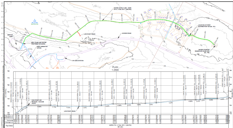
I could use some feedback on the following application. I'm wondering what I need in terms of air valves for this 1km long, small diameter, low pressure pipeline. Drawing attached.

1) 2" diameter, 1km long pipeline. 2 high points where air can collect. Q = 10 GPM.
2) Same as above except 4" diameter, Q = 50 GPM.

Working pressures won't be more than 50 psi.

These are obviously very small diameter pipelines. I'm wondering:

a) What would you recommend for air valves? Standard practice and literature would dictate I need a combination air valve at every high point. However, in practice I've seen many similar small pipeline applications where no air valves exist at all. Most of the air will be evacuated through the end of the pipeline on system startup, but there could be some pockets left at high points.
b) should I be concerned with entrained air buildup at highpoints? How long does it typically take for entrained air to gather at high points? This pipeline is in operation for about 4 months and drained yearly.
 
 https://files.engineering.com/getfile.aspx?folder=0e2815b0-9b3b-4b88-8a0c-70fd6f64b01d&file=Drawing.png
Replies continue below

Recommended for you

download.aspx_tbpwlb.png


A continually rising pipeline will tend to move air to the outlet, That's what you have there, so it is unlikely to need air release valves.

What can be more important is the velocity of water in the system. If it is above 1m/s (3.5 ft/s), air will be carried along with the flow, basically not collecting anywhere, however vapor lock can become a danger upon shutdown, when water may tend to collect at high points.

--Einstein gave the same test to students every year. When asked why he would do something like that, "Because the answers had changed."
 
Thank you for the response. That makes sense. To follow up, although overall the pipeline appears to rise continuously, there are in fact a couple of high points. These are gently sloping dips over lengths of maybe 50m.

In terms of vapor lock, I am not worried about vacuum conditions collapsing the pipe because the pipe is capable of withstanding full vacuum pressure.

There will be low point drains.

Regards,

-Andrew
 
Slight downward, or flat slopes are not significant, as water will move ahead by gravity. Some bubbles may be trapped, but when the velocity reaches 0.5 m/s, they should be on the way out. 1 m/s is enough velocity to even move bubbles directly downward, if they have to cross a low point ahead.

Vapor lock can be a problem to clear on startup, if you have multiple steep slops and high head differentials from low to high points. The necessary head to clear them tends to add up, but that condition is not evident here.

--Einstein gave the same test to students every year. When asked why he would do something like that, "Because the answers had changed."
 
Don't bother with air valves.

Not needed.

Just pump at 1m=sec or even lower given the low angle.

Our just send a small foam pig down the line.

Remember - More details = better answers
Also: If you get a response it's polite to respond to it.
 
Yes it's a very low angle. Change in angle less than 5%.

However, velocity is low at 0.35 m/s. I had to upsize the pipe diameter in order to avoid excessive friction loss. (I'm using an existing pump). I could change the pipe size to 1.5" which results in a velocity of 0.53 m/s.

Is there any literature you know of that I can reference for this determination I do trust your judgements but need a backup for my calc files.

Thank you kindly,

-Andrew
 
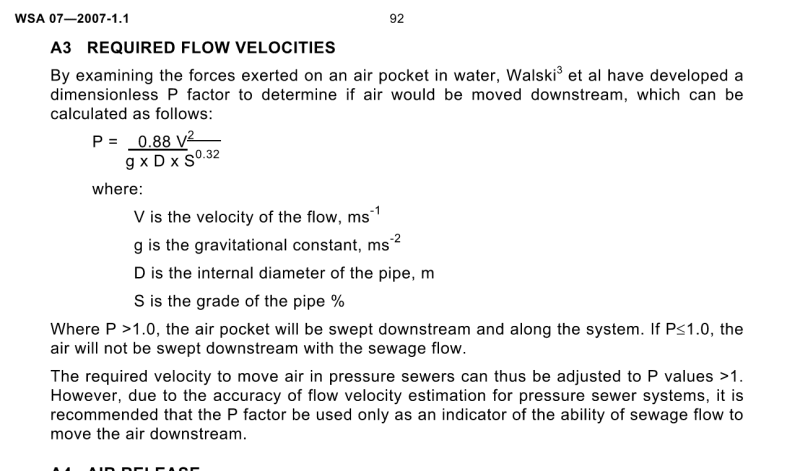
I remember reading some literature (possibly related to low pressure wastewater pump systems eg e-one, found it below from WSA-07) where there was a formula based on changes in pipe grade to determine if an air valve was required, as flow would be able to carry bubbles with it. as the air pocket forms you get localised cross-section reduction at that point so the velocity increases past the bubble until lit gets to the point it caries the air with it, obviously much trickier if you have a steep high point.
Screenshot_2024-05-30_100151_mcgray.png
 
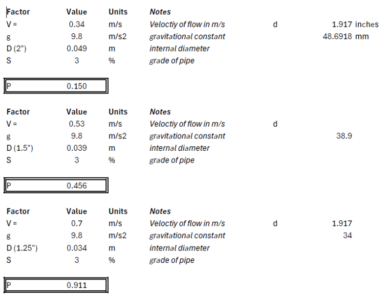
That is very helpful. I completed that calculation for 2", 1.5", and 1.25" pipe sizes and corresponding increasing velocity.

It seems the velocity does indeed have a major impact on the ability to move air bubbles. At a 1.25" pipe size and flow velocity of 0.7 m/s, I almost reach the required P value, but not even.

That said, the theory that a localized increase in velocity due to an air bubble formation, moving the bubble downstream, makes sense.

Values_uvjmue.png
 
You could always just build up a decent volume of water in the tank and then flush downwards at higher flowrate to remove the air pockets?

Don't neglect the possibility of using a pig. Small 2" pigs exist.


Remember - More details = better answers
Also: If you get a response it's polite to respond to it.
 
Hey @LittleInch, thank you for the response. I couldn't click on the first link, does it work for you? Can you re-post it? I would be interested in seeing it.
 
Thank you @1503-44. Some good resources in there.

-Andrew
 
Final thought on this. If I am filling up this pipe for a pressure test and doing so at a relatively low velocity (say with a garden hose of 3-4 GPM) - a velocity low to evacuate trapped air at high points - how would you tackle that? I could think of:

A) simply finding a pump capable of higher flows to fill the pipe up faster
B) Use a foam pig as mentioned earlier

Any other ideas?

Cheers,

-Andrew
 
Status
Not open for further replies.

Part and Inventory Search

Sponsor