brandnew1
Aerospace
- Apr 9, 2010
- 73
Hi all,
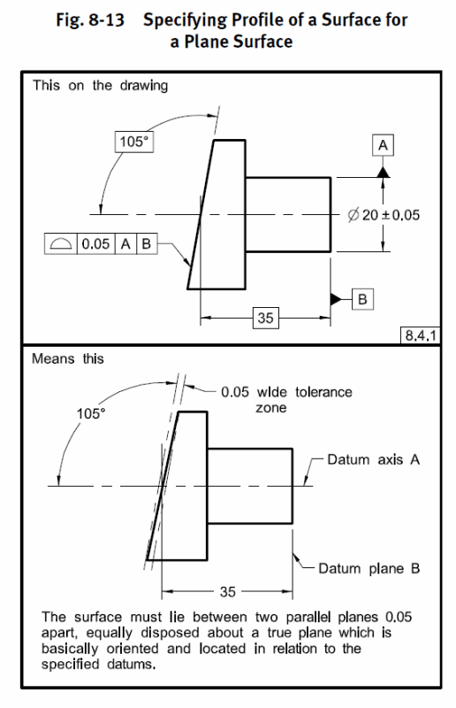
When it comes to profile of surfaces i understand it to be a form and location tolerance of plus or minus half the value given.
The attached image reflects a profile of surface to datum a and b of .005 which i believe it gives tolerances of +/-.0025 for all BASIC dimensions called out.
However my question relates to tolerances when it comes to Angles. Examples i have seen when it comes to profile of surfaces all seem to just show theoretically perfect lines at a specific angle with a spacing of half the profile value. But im completing a PPAP for the customer and i need to put the upper and lower limit.
Can someone give some clarification regarding the attached pdf.
To reiterate, my understanding of profile of surface gives a plus or minus tolerance of .0025 (attached pdf) for all the BASIC dimensions (even the intersecting points) but angle wise i'm not so sure about. (i figure if the .175 and 1.985 BASICS are within +/-.0025 then it really isn't too critical - but i would like to see if there is a more solid answer).
P.S. i'm basing this question also based on another thread which the individual indicated, "Option 2 is to apply GD&T specifications to control the outline. A profile tolerance of 1mm allows ±0.5mm of wobble along the edge, making it equivalent to a ±0.3° tolerance, but it will not be as expensive. This is precisely the situation where GD&T works." - [URL unfurl="true"]https://www.eng-tips.com/viewthread.cfm?qid=284803[/url]
Thank you

