Continue to Site

Eng-Tips is the largest engineering community on the Internet

Intelligent Work Forums for Engineering Professionals

  • Congratulations KootK on being selected by the Eng-Tips community for having the most helpful posts in the forums last week. Way to Go!

Questionable true position callout 2

Status
Not open for further replies.

End_User

Aerospace
May 23, 2019
8
Hello all.
First time post! :)

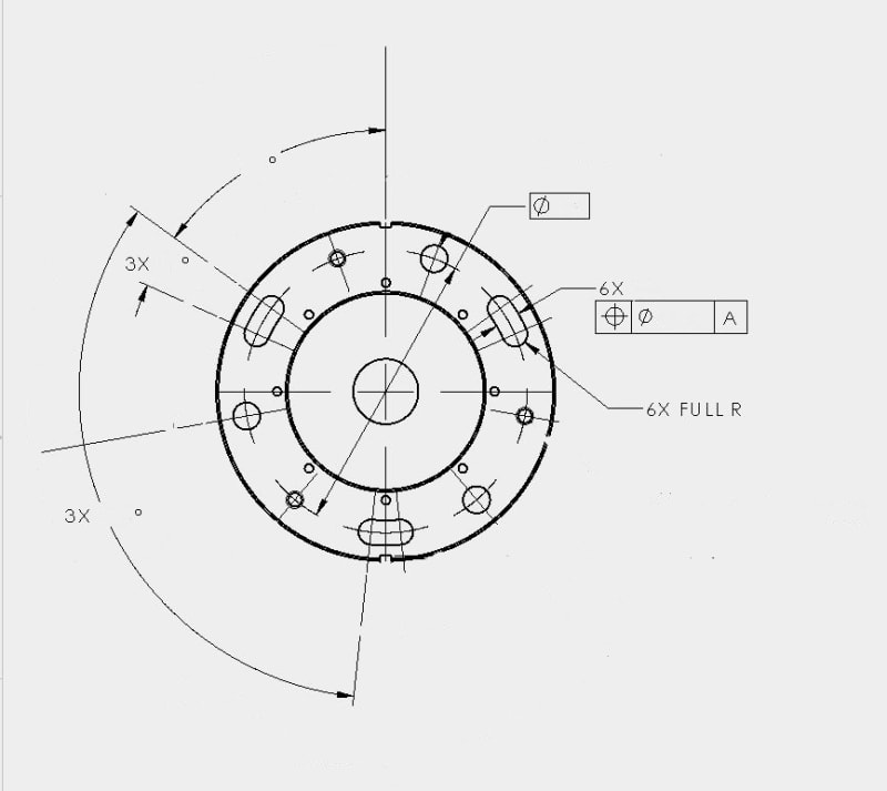
I have simple circular part with a 6 hole bolt circle pattern and a T.P. calout.
The confusion arises from the true position callout being connected to a width dimension and not a hole/diameter.

First, there are only three slots not six.
Secondly, A width has no inherent position nor does it imply the use a diametrical tolerance zone.

I'm generally confused as to what the designers intent was here and I know from previous experience that getting a timely answer from this customer is not possible.
So I guess a best collective guess from my peers seems like the next best option.

ideas, thoughts, interpretations, humorous observations all welcome!
Slot_TP_xm3fbz.jpg
 
Replies continue below

Recommended for you

I'll get this started. I consider the 3 holes and the 3 slots different patterns of features. At a quick glance I would look at Bi-directional Positional Tolerancing para 7.4.4 (2009) for the slots and conventional position for the holes. I would use the Simultaneous Requirement para 7.5.4 (2009) - same datums - to link the two patterns together as one.

Certified Sr. GD&T Professional
 
I would agree with mkcski. By the way, what IS datum A? If it's flat surface parallel to the projection plane, then it's not so bad.

"For every expert there is an equal and opposite expert"
Arthur C. Clarke Profiles of the future

 
Good point.
Datum A is the bore at the center of the of bolt pattern.
 
In the examples I have found of for Bi-directional Positional Tolerancing of slots there are two dimensions provided, one for the the width and another for its length.

Only width is provided here.. So how would one interpret the boundary condition without it?
 
I would consider the end-radii non-critical features that only have to miss whatever engages through the slots. If true, I would dimension them by an "inside" arc-length (not center to center) with limit dimensioning (not GDT). The end radii could be dimensioned per 1.8.4 (2009).

Certified Sr. GD&T Professional
 
Ahh , i found that if only one direction is specified, then it applies to both.
 
Where did you read this?

Certified Sr. GD&T Professional
 
7.4.5.1.

(c) In Terms of the Boundary of an Internal Feature of Size.
A positional tolerance applied to a feature of size establishes
a control of the surface relative to a boundary.
While maintaining the specified size limits of the feature
of size, no element of its surface shall violate a theoretical
boundary of identical shape located at true position.
The size of the boundary is equal to the MMC size of the
internal feature of size minus its positional tolerance. See
Fig. 7-34. The term BOUNDARY may be placed beneath
the feature control frames, but is not required. In this
example, a greater positional tolerance is allowed for its
length than for its width. Where the same positional tolerance
can be allowed for both, only one feature control
frame is necessary
, directed to the feature by a leader
and separated from the size dimensions.
NOTE: This boundary concept can also be applied to other irregular
shaped features of size — such as a D-shaped hole (with a flattened
side) — where the center is not conveniently identifiable. See
para. 8.8.
 
it states positional, but they are referring to the boundary
 
Yes. But do you want to apply the "boundary" condition to the slots? Did you consider my earlier post discussion the function of the end-radii? Either one will work but "boundary" may be more difficult to interpret and inspect. Your call

Certified Sr. GD&T Professional
 
"I would consider the end-radii non-critical features that only have to miss whatever engages through the slots"

No, I wholeheartedly agree! Not looking to make any more work for myself than necessary. :)

I was just stating how it would apply if only one boundary condition is provided like in mine as the example in the book was defined fully.


End User,

The excerpt you posted is in reference to the Boundary concept in conjunction with MMC. While perhaps a single leader line could be utilized in a similar manner with RFS as in your example (it would no longer be the same as the BOUNDARY concept as that requires MMC I believe), I think you're missing a key part of the paragraph "Where the same positional tolerance can be allowed for both, only one feature control frame is necessary, directed to the feature by a leader and separated from the size dimensions." Its hard to tell from your figure as it seems to be censored of dimensions, it seems that the FCF in your example is attached to the width dimension - which does not follow from the standard *if the intent is to control both the length/width with the same size tolerance.

Its hard to tell what is meant by the 6X annotation - perhaps they meant to group the 3X slots with the 3X holes. This would be the improper way to do it as mkcski pointed out these are two separate patterns that could be held together with simultaneous requirements. The only proper interpretation of the drawing I can see as drawn is that the position FCF only applies to the width of the slot therefore the length of the slots (between end-radii), their orientation (clocking), and the position of the 3X holes are uncontrolled.

*Edit
 
When considering Position interpreted not by "boundary", the tolerance zone should limit an axis or a center plane and should either be cylindrical or 2 parallel planes the tolerance value distance apart. How should the toleranze zone look like for Position applied on the curved slots? 2 concentric arcs the tolerance value distance apart? Haven't seen something like that covered by the standard.
 
Burunduk: See figure 7-29 (2009)

Certified Sr. GD&T Professional
 
Chez311 I see that now.

The 6x on the print is indeed followed by the width dimension.
 
For sure, the drawing needs a lot of work for correct interpretation per 2009.

We didn't "chase down" the datums. If the part is thin, and Datum A is the hole in the middle as you said, there will be problems with a repeatable ref frame.

Certified Sr. GD&T Professional
 
mkcski,

That was my initial thought as well*, however I think Burunduk may be on to something. The bidirectional tolerance zone shown looks at first brush to be easily applied to a curved slot, however the "slot shaped" tolerance zone just dictates the area where the UAME axis of the hole may fall within. Applying the same concept to a curved slot, what is the UAME? The more I look at it the less I feel that positional tolerancing in this manner with RFS can be applied - perhaps it requires MMC and the boundary concept. What do you think?

*Edit - in regards to the bidirectional tolerance zone
 
Leaving for the day. I'll respond tomorrow.

Certified Sr. GD&T Professional
 
Status
Not open for further replies.

Part and Inventory Search

Sponsor