Eng-Tips is the largest engineering community on the Internet

Intelligent Work Forums for Engineering Professionals

Questions regarding Fan Performance Curve 3

Status
Not open for further replies.

David_HVAC_Learning

Mechanical
Sep 11, 2023
8
0
0
US
Method_of_Obtaining_Fan_Performance_Curve_oob0kg.png


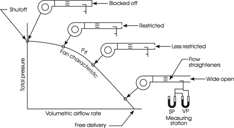
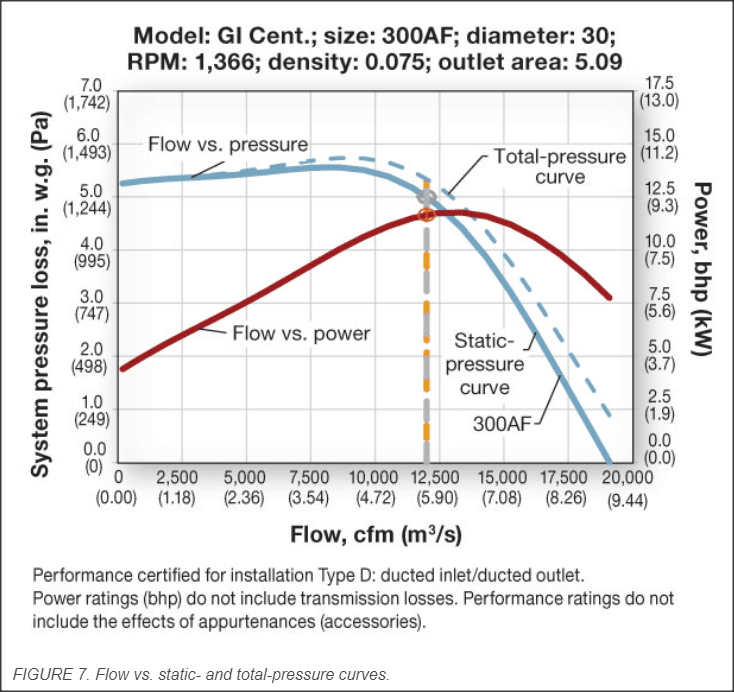
So, the above figure, is almost the same figure that is shown in the 2016 ASHRAE Handbook - HVAC Systems and Equipment (Page 21.4) with Total Pressure being defined as the fan total pressure at the outlet minus the fan total pressure at the inlet. This figure is shown in the handbook when it's discussing how a fan performance curve is obtained during testing and such. Is it correct for me to say that the reason why the total pressure (difference in pressure) on the performance curve is zero when the airflow is highest is because once the airflow reaches a certain point, the amount of friction/headloss that is produced from the fan during testing becomes equal to the positive pressure that the fan is trying to create? So in other words, they cancel out? Is my understanding correct or is there something else to it? Please let me know what you think. Thank you.
 
Replies continue below

Recommended for you

I think that your confusion comes from:

1. The Y-axis label of the figure appears to be wrong. It should be "static pressure".
2. The stated definition of "total pressure" is wrong and incomprehensibly circular.
 
Total pressure is a bit odd, but this appears to be Differential pressure which is quite normal to show.

The curve though will never reach zero as that is physically and practically impossible. This is a simplification of a fan curve and it really should stop at the point shown where it says "wide Open". To continue the line to the x axis is just plain wrong. IMHO.

If this was say an atmospheric inlet then you need to have some pressure less than atmospheric in order for air to flow into the fan. Similarly you need pressure a bit more than atmospheric for the air to flow out of the fan.

Now those pressure might be very low, but the differential pressure is NOT zero if there is flow, especially lots of flow.

Remember - More details = better answers
Also: If you get a response it's polite to respond to it.
 
I think MintLup is right, it should be static pressure. But we don't know the context (like any title or text referring to or explaining this chart).

You also should not assume the bottom is zero if it isn't labelled a such. Sadly, many graphs don't start at zero to create some more dramatic effect.
 
Okay so from what I've gathered, essentially I'm getting confused because I'm assuming that the x-axis is zero which is not the correct assumption to make because it would make no sense for air to be flowing if there is a zero pressure differential. Okay. That makes sense. Thank you for your responses.
 
The very right end of the chart is an extreme case when there is no EXTERNAL static pressure (external to the fan) generated. Basically like one of those ventilators that blow air on people. Once you add a duct (and add static pressure), flow ill be reduced and your operating point moves the the left on the curve.
So, within the fan, there is static pressure gain, but that gets converted to velocity pressure outside the fan.

in HVAC, this would be a transfer fan.

The very left of the chart is another extreme you don't want to have. it would be blocked flow. Obviously you could achieve zero flow without buying a fan. This would be in the surge region of a fan anyways.

 
I believe that a blower curve is similar to a centrifugal pump curve. The sloping shape of the centrifugal pump curve is due to the curvature of the impeller blades. As the fluid leaves the impeller there are two components of velocity - one tangential to the impeller perimeter (in the forward direction - the direction of rotation) and one tangential to the blade (which is backward curved) so there is a component of this velocity that subtracts from the velocity that is tangential to the perimeter. The resultant of these velocity vectors is the absolute velocity of the fluid. This velocity head is converted to pressure in the pump volute. This is the basis of the pump affinity laws - if you increase the pump speed the velocity vectors of the fluid exiting the impeller increases in direct proportionality with impeller speed - since pressure head = V[sup]2[/sup]/2g then P2/P1 = RPM2[sup]2[/sup]/RPM1[sup]2[/sup].

At lower flows the resultant velocity is higher than at higher flows since the radial velocity vector tangent to the blades is smaller so that the net velocity approaches the velocity of the periphery of the impeller. As the flow increases the radial blade tangential velocity increases and the direction is such that the resulting velocity and therefore velocity head (and converted pressure head) gets smaller at higher flows, since componet of this velocity is in opposite direction than the periferal velocity. This causes the shape of the centrifugal pump curve to slope down as flow get higher. Therefore at different flows a centrifugal pump is capable of developing a different pressure head. The resulting flow is when the system pressure drop at a given flow matches the pump pressure output capabilities at that same flow.

I assume centrifugal blowers are similar. The shape of the blades determine the velocity vectors of the fluid exiting the impeller and hence determines the pressure output for a given flow. So at each point of the curve the pressure shown is the pressure able to be developed by the fan at the given flow. At the end of curve the fan does not produce any pressure but only flow because the velocity components exiting the impeller cancel so there is no net velocity head that is converted into pressure head - only velocity which produces flow. And at zero flow there is only velocity of fluid exiting the impeller that is tangential to the circumference in the direction of rotation and no backwards radial velocity component - hence maximum pressure output.
 
The OP was correct: the discharge velocity pressure matters in a technically correct reading of a fan curve.

But the distinction is often ignored. There is a large amount of sloppiness in HVAC “engineering.” We get away with it because there are large uncertainties and safety factors. It is often a "success" if a value from the design phase is within 10% of "reality."

An attempt to be technically correct is often met with disdain. A fuss over the velocity pressure produced by a fan can provoke derision and/or glazed stares. The OP is to be commended for actually understanding what they found.

Unhappily, the OP retreated with an incomplete statement: “It would make no sense for air to be flowing if there is a zero pressure differential.”

What kind of “pressure differential” – static pressure or total pressure?

Good pump curves plot “total dynamic head” versus flow rate. The discharge is often smaller than the suction, so the discharge velocity ... and velocity pressure ... at the discharge are greater than at the suction. Ideally, one would account for the difference in velocity pressure between the suction and discharge. But almost no one does – and we get away with it.

Similarly, I have found it to be rare that anyone cares about the distinction between the “total pressure” developed by a fan and the “static pressure” developed by that fan.

I am reminded of the thread “Glycol Corrections” thread:


Even if one acknowledges the differences between the properties of water and glycol, the extent to which they are willing to care about them is limited.

I don’t recall ever seeing a TAB report where a pressure difference was reported in terms of “feet of glycol” – let alone with it corrected for the actual density of glycol at the operating temperature.
 
Total pressure is the sum of static and velocity pressures (usually), but fan curves are no good if they account for velocity pressure. The curve is simply the static pressure at the outlet minus the static pressure at the inlet.
 
"fan curves are no good if they account for velocity pressure."

No good for whom?

It benefits the vendor to sell the higher number. Then a shortfall in performance can be blamed on the engineer because they didn't account for what the vendor actually advertised.

Pump vendors routinely sell "total dynamic head," which includes an increase velocity pressure that I always ignore. So far, I have gotten away with ignoring the distinction between the total dynamic head claimed for the pump and the static pressure boost my design needed.

AMCA should be consulted for definitions:

3.1.26 Fan total pressure
The difference between the total pressure at the fan outlet
and the total pressure at the fan inlet.

3.1.28 Fan static pressure
The difference between the fan total pressure and the fan
dynamic (velocity) pressure. Therefore, it is the difference
between static pressure at the fan outlet and total pressure
at the fan inlet.

3.1.39 Free delivery
The point of operation where the fan static pressure is zero.

8.2 Performance graphical representation of test results
8.2.1 Coordinates and labeling
Performance plots shall be drawn with the fan airflow rate
as abscissa. Fan pressure and fan power shall be plotted
as ordinates. Fan total pressure, fan static pressure or both
may be shown
.

Much of AMCA's funding may come from manufacturers. It is in the interest of manufacturers for AMCA to be okay with catalogs presenting curves for fan total pressure. AMCA allows either or both types in curve in 8.2.1. Caveat emptor.

Depending on how close to the edge one's design is, it may or may not be important to read the vendor's fine print to see if it is necessary to account for the distinction between fan total pressure and fan static pressure.
 
No good for me. And I hope it would be no good for most people.

Take a 1000 cfm fan designed at 4" TSP. The fan shutoff head (or dead head) is say, 6". These are numbers for typical systems. The 4" TSP is only meaningful if it is the outlet static minus the inlet static.

Now let's say the inlet duct is very large. 16" dia. The velocity pressure at the inlet is very low at .03". But for the same 1000 cfm fan, the outlet duct is much smaller (let's say 4" dia.). The velocity pressure is 8.2".

8.2" - .03" is about 8.2". Where does that show up on any fan curve that dead heads at 6"?
 
If the fan is tested with inlet duct approximtely same size as outlet duct then the differential static pressure indicated on the fan curve is the total pressure, correct? So if you have the case you presented above (and assuming that the 4" duct discharges directly to atmosphere and does not increase in area so that pressure regain occurs), the fan can only put out 4" at 1000 cfm, but with 4" duct the velocity head itself is 8.2" at 1000 CFM so the flow will decrease until the system curve matches the fan curve considering head needed for velocity and friction loss.
 
Close, but you're overthinking it. Contrary to popular belief on this issue (and possibly others), size does not matter. That's the beauty of a fan or pump curve. Stick them in any system regardless of sizing of inlet or outlet pipes or ducts, they will only produce the flow that the total STATIC pressure across them defines based on the curve. If we try to make a fan curve that incorporates velocity pressure, who knows what it would look like - might be a sideways helix thing or something that looks like an infinity symbol.
 
I don't know what you are saying in your last post. The static pressure across the fan is really the total pressure since I believe during testing the outlet duct is same size as outlet of fan and the inlet duct is same size too. So the static head is the total head availble. If you immediately reduce to a much smaller duct at the outlet this takes some of the availble head to be converted to velocity head. In this case if you put a pitot tube in the flow just at the exit in the smaller duct then you will still measure the total pressure head at flow as on the fan curve but some will be static and some will be velocity pressure. In your example above most will be velocity pressure with negligible static pressure.
 
AMCA knows what a fan curve that incorporates velocity pressure looks like:
Snap_2023-10-07_at_00.22.01_wkupfn.png


Also from AMCA:
Section 2: Fan Static Pressure (FSP)
This is important because this is used for ratings.
Equation
FSP = SP at outlet – TP at inlet

We usually get away with ignoring the velocity pressure at the inlet when selecting a fan. This simplification may work to the vendor's advantage if the engineer claims the fan is not performing -- based on readings of static pressure alone.

Expanding the formula for FSP:
FSP = SP at outlet – TP at inlet
= SP at outlet – (SP at inlet + VP at inlet)

Rearranging:
SP at outlet – SP at inlet = FSP + VP at inlet

Though it is commonly measured in the field, the AMCA document linked above does not include a definition for "SP at outlet – SP at inlet."

For the purpose here, define "Measured Static Pressure" as:
MSP = SP at outlet – SP at inlet

So MSP is always greater than FSP when the velocity pressure is greater than zero.

To whose advantage that is may depend on the situation.

While fan curves may neglect the velocity pressure at the outlet of the machine, pump curves do not:

H= (Z[sub]2[/sub] - Z[sub]1[/sub]) + (h[sub]2[/sub] - h[sub]1[/sub]) + (h[sub]v2[/sub] - h[sub]v1[/sub])

We usually get away with ignoring a change in velocity head when selecting pumps. Again, this simplification by the engineer can work to the vendor's advantage in some cases.
 
Chasbean1, do you mind diving a bit more into what you said in regards to duct sizing not matter?

If I'm getting it right, you're saying that according to a fan performance curve, it does not matter what size duct they used in testing for the inlet or outlet, the fan will perform the same for whatever duct size we end up actually using in the field. So if I've got this right, what you're basically saying is that, if a fan performance curve says that a fan can create 5" of static for a CFM of 5000 then we can be assured that whatever duct system we put it in, the fan will create an airflow of 5000 and produce 5" of static. I guess the problem I'm having trouble with this is that, if we put the fan with a very small duct, and then have it produce an airflow of 5000, the velocity pressure would be through the roof, and so I would assume if the velocity pressure increased then the static pressure that the fan creates would have to decrease as well, no? But according to what you're saying (if I've got it right), the static pressure would still stay at 5". Please let me know if I've misunderstood what you said, and if I didn't, could you please elaborate more as to why you think this is the case?

If I think about for a bit, I would assume that the reason why that works is because yes, we would get the same airflow, the same static, and still have an increase in velocity pressure, but the consequence of that would be that the small duct size would create a huge major head loss value and thus we would not have a lot of duct length to play with in our system. Not sure if that's correct.
 
Status
Not open for further replies.
Back
Top