Eng-Tips is the largest engineering community on the Internet

Intelligent Work Forums for Engineering Professionals

"new" roll/sway bar concept

Status
Not open for further replies.
Morning all,
referring to magazine Race car Engineering V9n1 Jan/Feb 1999 page 76 would anyone care to make comment or does anyone know if this layout has gone anywere, I cannot see any advantages and I do not understand the statement "fully floating spring damper unit". I was approached recently about this concept and recall reading it albeit 15 years ago, have reread but it still does not make sense to me apart from the fact that I would not like to do the "calcs" to determine the value of the
'spring/resistance" to bending, don,t know what to call it! Comments etc greatly appreciated.
Golfpin
 
further to the query on anti roll bars it was named "nic-link" after the designer Nick Walford designer of the Radical motor cycle engined race car.
thx golfpin
 
Thanks for the link Greg but have you any thoughts on the concept, as I said the term "fully floating shock" puzzled me.
Thanks again.
Golfpin
 
Hi Golfpin

I may see this wrong, but I "think" the term fully floating spring/damper unit refers to the fact, that the spring and damper get "double actuated" [not sure if this is a good term], similar to concepts you find in some motor cycles.
In simple terms, both ends of the spring/damper move towards each other. In a conventional layout, one end would be fixed to the chassis, and only the other would move towards this "fixed" point.
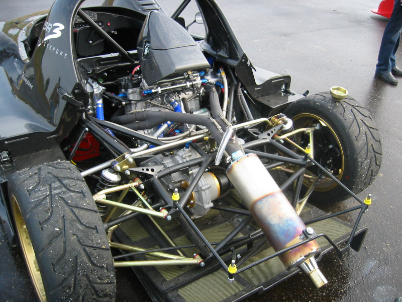
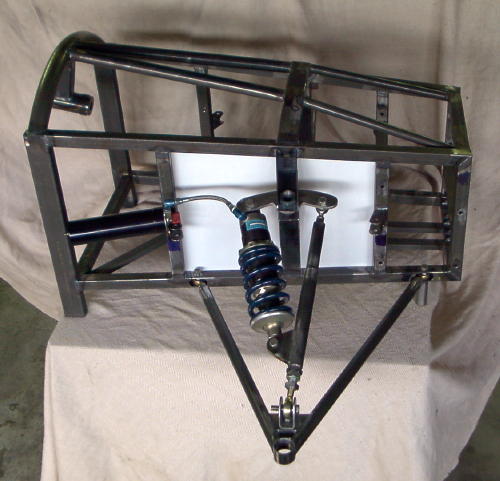
Here, if we assume the body stationary in space for a moment, while the wheel providing a input, the lower wishbone has two connections. One is the lower eyelet of the spring/damper unit, and the other connects to a small pushrod which then actuates a rocker, and this rocker reverses the direction of the motion by 180º. At the other side of the rocker, the upper eyelet of the spring damper unit connects.
So the while the lower part of the spring damper is moving upwards, the upper is - not only stationary, like in a normal system - it is moving downwards, towards the lower part. So for a given input from the wheel you almost double (the true rate will depend from the rocker motion ratio) the relative movement of your damper and spring. For a given spring, you would get more force, and for a given damper more velocity, which should result in a higher force as well.
You can optimize the motion ratio for a given wheel input.
At the rocker connects another link - the "nic - link" which causes an actuation of the other sides spring/damper unit as well.
The link, has a "kink" in it, where it will deflect in relation to the force, so not all the movement get's transfered to the other sides spring and dampers.

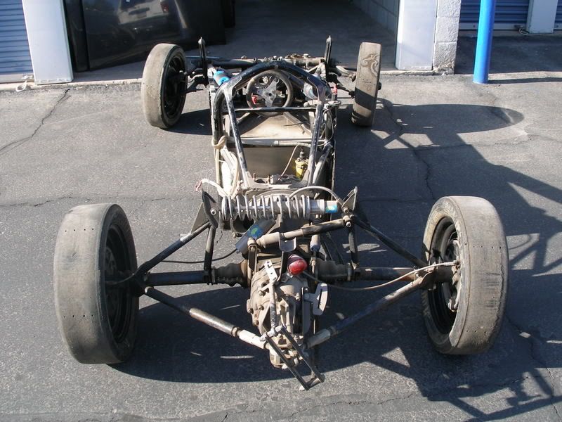
here two photos, which should illustrate the concept quite nicely.

139-3904_img.jpg


60e6224d2823753db3b7378a274e6fbe.jpg


thats my take on it, but I could be wrong

btw, any news/progress with the brake actuated diff lock system, we have been talking about a while ago?
Cheers
TC3000
 
Morning TC,
Thank you so much for the pics and the explanation very good of you, don,t know if the query will go anywhere. The question came from a very good friend who has the drive in Lola t70 replica but I think he wants to build a Lotus 23 replica !!!very capable craftsman but the ideas to execute the project get a bit away from the replica concept.
Re the hand brake/diff idea I got very excited but when I approached the owners all I got was a blank look, they did not have a clue as to what I was talking about! I should,t get upset by the ignorance but they are scratching at the back end of a club race.
This brings me to a related point, in 1967 I was working next to the Chequered flag set up in london they ran 2 F3 cars with the DAF variomatic gearbox[ yes a little 1000c screamer with auto type box the one driver was Mike Beckwith] I digress a little, the chief mech/manager was Chas Beattie a very very capable all rounder he also used to help an up and coming Australian name of Tim Schenken on a lotus F3 or such, he fitted a varation on the front anti roll bar theme by splitting it in the middle and anchoring it.
The idea was not new but the application was to me, on discussing it, he [Beattie] said that he wanted to separate the roll resistance from the roll resistance of the springing medium, I think this has been attempted a few times one that comes to mind is one of Len Terry,s earlier cars had this in mind with a single crosslinked shock I ask this broadly, does the Radical layout fall into this and I recall some years ago F1 went the route of a single front shock and then at one time I think 3 shocks are these all on the same concept? Saw a comparitive layout on the front of a Pilbeam LMP car that was tested here in RSA last year but Mike Pilbeam tried to explain to me that was an attempt to control anti-heave..Any comments appreciated hope not too disjointed.
with thanks Golfpin


Hi, TC small ? on the last of those very good pics I see a small rose joint and link attached to the lower wishbone and incline up but then disappears behind the rack boot and a few other bits, I cannot figure out what it is or does ???? anyone share a thought as to what it is.
Golfpin
 
My take:

The 'fully floating spring damper unit' and the 'nik link' are two distinct things.

The former increases damper travel relative to wheel travel and possibly introduces a rising rate correction to the otherwise falling rate you would get if the spring damper were direct mounted. I suspect early Radicals had direct mount spring dampers that were larger, heavier and falling-rate, and this arrangement is a later fit to the same basic vehicle package.

The latter is the cheapest / easiest packaged way of adding a (dare-I-say crude) anti-roll suspension element. But I would not like to do the wheel rate calcs... Given they are rated 'soft' 'medium' and 'hard' I suspect no-one else has taken on the challenge either...

Regards, Ian
 
Hi Golfpin

Glad to hear, that you found the photos useful.
Sorry I'm on a mobile, at the moment, and can't "draw" a sketch or something, but you have to think about the rocker having three "legs/arms", but you only see two in the photo.
The small pushrod, you see connects to the rockers "invisible" leg/arm. When this pushrod moves upwards, it causes the the "leg/arm" of the rocker, which is connected to the damper top mount to move downward. It's a 180º reversal of the motion direction - think about a "classical" engine rocker, in a engine with a single low camshaft.
The best illustration, to give you an idea of the concept, I could find quickly, is the following.

clip_image004.jpg


just that in our case, the damper/spring unit would not connect at the center of rotation of the swingarm, but a bit more towards the right. So it would contribute a upwards motion, while the rocker is pressing the other side down - I hope that makes some sense.
It's easy to sketch, but a bit difficult to explain for a none native English speaker.

As for your other question, I'm with Greg on this one. The way I understand it, which could be wrong, you would "just" at a torsional spring to each side. It would stiffen the main suspension, but would do so in both heave, roll and single wheel bump.
It would be like trowing the anti roll bar out completely, and fitting stiffer main springs instead.
Now, without seeing the system, and how it is activated, there is the possibility, that you introduce a rising or falling rate effect.
So you perhaps, create a form of progressive (or digressive) spring rate with this, while using a linear main spring, but it doesn't do anything in "roll" specifically, unless, it does add spring rate to one side while reducing it at the other, due to some kinematic effects. Without a photo or illustration, is a bit difficult to say, with any degree of certainty.

In regards to the shown Radical system, I think Ian (murphia) is correct, and I would see it the same way.
You have to systems at work. One is used to be able to modify the motion ratio of a double wishbone suspension with an diagonally mounted spring/damper unit, which employs a rocker. Similar systems you find at the back of motorcycles in different form pro-link etc.

The other is the function of the "nik-link or nic-link" which is used to link the action of one suspension side to the other. Like you do with an ARB (or sway bar)
The principle is "similar" to a "heave spring" or "3rd spring" but, while a "heave" spring would connect to the same side of the rocker, and only work, when the wheels rise or fall together, the "nik-link" is connected to the opposite side of the rocker on the other side.
Making it only/mainly work in roll.
To be able to "tune" the effect, it uses the "kink", at this point, it will flex, and thereby only transfer a part of the motion to the other side. You could use a straight link and put a spring in the middle, which would then look like a "heave spring", but connected to the opposite sides of the rocker.
The "Kink" area is quite highly stressed, and has caused issue on some cars for some sizes of links used. see photo below.

9tCDt6Ap.jpg


Hope this helps. When I get back to the office and have the time, I may attempt to sketch it - if it is still not 100% clear.
 
o.k. I found another photo, which may helps to get the gist of the idea about how the "floating" spring/damper unit is working.
it is not exactly the same system as used on the Radical, but the principle is the same - IMHO
the "nik-link" ARB would come "on top" of it, but one isn't needed for the other to work, it just happens that the Radical employs both concepts.

ftclip.jpg
 
o.k. - I trust, this photo will answer your question about how and where the small pushrod connects on the other photo.

Enjoy:

cfa34d45-38fe-42e3-ab11-5e008b698663.jpg


best regards

TC3000
 
small addition:

ReN3XvI.jpg


EXLYaPs.jpg


I think, this should clear it up, where the "nik-link" connects and how it is supposed to work.
 
Interestingly increasing the motion ratio of the shock absorbers is not always a good thing. One of the big problems with shocks is seal friction, and by increasing the MR you increase the effect of friction. This causes a condition known as boulevard ride where the suspension is effectively locked, and the car rides on the tirewall stiffness. This is essentially undamped. One way around this is to tune the rubber that is in the shock absorber load path to provide some damping (this has its own pitfalls), or to reduce stiction by various expensive or nasty design changes in the shock. Much better to engineer your way out of the problem before it starts in my not very humble opinion.

Cheers

Greg Locock


New here? Try reading these, they might help FAQ731-376
 
10:15 pm To all those who have taken the trouble to reply, a very big thank you and especially Tc for the fab pics and the explanations again opened a huge window. To Greg that tit bit on shocks is amazing stuff, thank you again to all.
Off for another sleepless night while I wrestle with these concepts and the god morpheous!!!!!
Golfpin
 
you are welcome golfpin - glad to hear, that you got something useful out of it.

in regards to your other inquiry, about heave &/or 3rd springs, you may want to take a look at his images

GR59-Detail-42.jpg


and I'm sure you have come across the typical Formula Vee layout before, this is one way, to implement a "heave" spring

66870d1360253632-custom-fabrication-thread-post-pics-stuff-you-have-made-rearsuspension-jpg

RearFrame.jpg


Please take a moment and read the content in the link below,, it's not the most technical explanation, but I think, it gives a fair idea about the different parts.
In order to try and understand the "nic-link" concept/idea/principle, pay attention to the illustration of what he calls the "roll damper" [navy blue diagonal item between the rockers] - imagine if this was not a damper, but a spring (or a spring/damper unit) connected to the shown points at the rockers.
This in a nutshell is - IMHO - the principle idea behind the concept, just the implementation is slightly different.

f1-suspension-internals-640px-1loppsow3yicx.jpg
 
I apologize for the rather poor/none technical quality of the illustration (Excel is all I have on this machine), but I hope nonetheless that it helps to illustrate the principle function of the "NIC-LINK" , and the underlying idea/concept.
In a nutshell, where a conventional ARB/swaybar makes use of a bar/tube in "torsion" the "NIC-LINK" uses the bar/tube in bending, around the bend/"KINK" area. Think along the lines of a column in a post buckling state. The difference is, that the "buckling" area/point is predefined and rather concentrated in this case.

TkyGTch.jpg
 
TC my thanks for all the effort you have put into the info and links you have passed on, for an ageing amateur it is inspirational, my thanks again.
Golfpin
 
Couldn't you achieve this with a coil spring instead of the buckling bar? Trying to use a buckling member as a spring in this way seems grossly non-linear (even ignoring non-linearities in the linkage itself), not to mention assymetrical side to side.

You could also potentially use a coil/damper system and put damping on roll rate, which is an interesting idea, not sure if it's been done with conventional ARBs?
 
Status
Not open for further replies.
Back
Top