Continue to Site

Eng-Tips is the largest engineering community on the Internet

Intelligent Work Forums for Engineering Professionals

  • Congratulations cowski on being selected by the Eng-Tips community for having the most helpful posts in the forums last week. Way to Go!

"torque" spec on saddle brackets?

Status
Not open for further replies.

ClocksNbells

Structural
May 11, 2016
2
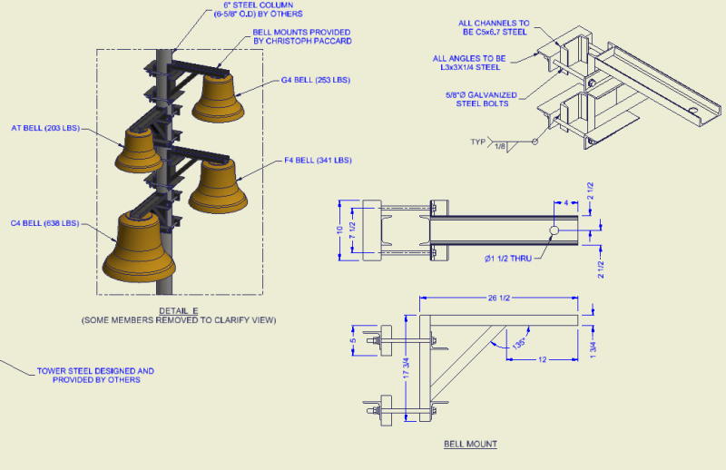
I've designed a clamp-on saddle bracket that clamps to a vertical pole. See attachment.
There are four of these brackets for hanging large bells.
The Architects are asking for a "torque" required to safely secure these brackets to the pole.

Initially, I was going to suggest the "turn of the bolt" torque method. But if my thinking is correct this doesn't apply because my brackets have an open space. Thus all the "plies" will not contact each other.

So now, I'm at a bit of a loss.

Is my thinking correct on the "turn of the nut" method not being valid?
How do I determine the torque required to secure these brackets?

Thanks.

Screenshot_2016-05-11_09.29.53_ggnpb9.png
 
Replies continue below

Recommended for you

Interesting detail... I take it you cannot weld to the 6" pipe column?

I have done something similar for a walkway (i didn't sleep for weeks) and my calcs were based on a level of clamping force which i related to a bolt tension and then a conservative torque number after all bolts are turn of nut tightened... Id say you may be good with either method but the turn of nut should be done after all nuts are snug tight and in place or some specific order or work.
 
I used a similar connection once for attaching some traction power stuff to a bunch of existing utility poles. The stakes, and budget, were quite high there so we ended up specifying a bolt tension and load testing a few in the shop. Some thoughts:

1) A agree, turn of the nut isn't strictly applicable here. it won't give you a very predictable amount of tension and may, in fact, damage some parts of the system (not too likely I would think).

2) Clearly, you need a minimum amount of tension as this is essentially a friction connection with respect to vertical load.

3) Each bell will induce a moment on its respective connection. The compression portion of that moment may well give you all the friction that you need. Might be tough to evaluate that reliably however.

4) I'd recommend talking to a local fabricator or testing agency to get their feel for the best way to induce, and perhaps verify, the bolt tension that you'll need to make a go of the connection.

5) Turn of the nut might be altogether useless in inducing a predictable bolt tension as tightening a bolt on one side will also significantly affect the tension on the other side.

I like to debate structural engineering theory -- a lot. If I challenge you on something, know that I'm doing so because I respect your opinion enough to either change it or adopt it.
 
Consistency of the torque is almost as important as the torque value itself. For that reason alone, I would not use turn of the nut method.

You could use load indicating washers (Direct Tension Indicator); however, those are designed and calibrated to high strength bolts so you might overtighted these bolts unless you decide to use high strength bolts (A325/A490). If you can use high strength bolts, "Squirters" would be a good way to go with these....purely visual indication of proper tension.

You have two slip conditions here....vertical slip from self-weight and rotational slip from wind loads. Those will likely have different friction areas to deal with.

As for using a torque wrench, you can calibrate to the bolts you are using to gain essentially any clamping force you desire. Assuming this project is somewhere in the US, you will likely be able to find a local testing lab with a Skidmore-Wilhelm device that will allow you to calibrate the wrench to the tension desired. You will likely need a 600 ft-lb torque wrench, though with a 5/8" dia. bolt, your final torque will likely be in the 250-300 ft-lb range.
 
Are 1/4"-thick angle legs going to be strong enough to provide sufficient resistance to a couple of stretched 5/8" bolts, and still remain in the elastic stress range for bending?
Dave

Thaidavid
 
I forgot to ask: are these bells for looks, or will they be actively rung? If they get rung very much, does your clamp design account for the (probably complex) dynamic vibrations in the entire assembly?
Dave

Thaidavid
 
Ron said:
As for using a torque wrench, you can calibrate to the bolts you are using to gain essentially any clamping force you desire. Assuming this project is somewhere in the US, you will likely be able to find a local testing lab with a Skidmore-Wilhelm device that will allow you to calibrate the wrench to the tension desired. You will likely need a 600 ft-lb torque wrench, though with a 5/8" dia. bolt, your final torque will likely be in the 250-300 ft-lb range.

I doubt you will need to torque these things that high for that amount of load. You can use the same torque wrench that mechanics use and not have to go through all the expensive calibration stuff. There ain't that many bolts.
Figure out the clamping force you need based on friction and back the required bolt tension and corresponding torque out of that.
 
Wow! Thanks for all the replies! I really appreciate y'all taking the time to respond.

The vertical pole is part of a tower by others. We are only supplying the support brackets.
The tower is not exposed to the elements. It has block walls, and louvers to shield the bells from any "real" wind-load.
The bells are static in location, but will include strikers to ring them. So there will be some vibration involved.
The site is located in North Dakota.

I can bump the 1/4" steel angles up to 3/8" pretty easily, if that's a concern.
But it seems that the bolts are only holding the clamps to the pole. The vertical weight of the clamps and bells will be "stuck" where they are due to the friction between the vertical pole and the steel channels.
Would I benefit from making the smaller channel pieces into a single piece to match the long "front" side channel?
Do I gain anything by adding a adding a third angle with two additional bolts?

I was really hoping the "turn of the nut" was a valid answer in the end. As counting on anybody having a torque wrench handy on a construction site seems unlikely. Thus, a more general "torque rating" would be more of a real world answer.

Thanks everybody!


Figure out how much torque you actually need. If a mechanic's torque wrench doesn't do it, maybe you can be comfortable telling them to use a cheater bar of a certain length if you know it gives you a huge factor of safety even if they push lighter or harder than you expect.
 
Similar to what XR250 is stating, to put some perspective to the magnitude of applied torque and resulting tension, this photo shows a 1/2" diameter 7-wire 270 ksi strand being tensioned to 25 kips using a 36" long, 600 ft-lb capacity, torque wrench. The applied torque was approx 200 ft.lb. Whilst the torque wrench was calibrated by a NIST lab, the preload was cross-checked using a vibrating wire strandmeter hooked up to a digital data-logger.


DSCF0843_grxnol.jpg
 
CNB...a 600 ft-lb torque wrench is fairly common. Many testing laboratories have them, many truck/diesel repair shops have them and many steel erectors have them. A mechanic's torque wrench usually does not go high enough for a 5/8" bolt to get a resonable tension/clamping force.
 
We have several torque-wrenches and one of the better manufacturers is IMPERIAL-NEWTON of Colorado Link. A 600 ft.lb capacity torque wrench, with NIST calibration, will set you back about $1,000.
 
Status
Not open for further replies.

Part and Inventory Search

Sponsor