y2k_o__o
Petroleum
- Nov 20, 2022
- 6
My current company doesn't perform any stack up analysis before they release product, and I am very new to this topic.
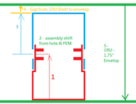
Here's the loop diagram for the shelf that consist of top and bottom chassis where screws are fastened through the side into.
1 - bottom of chassis to PEM centerline
2 - assembly shift from top chassis clearance hole
3 - PEM centerline to top of chassis
4 - Gap identified as a point of interest in tolerance stack-up analysis
5 - 1RU envelop

However, I was reading some online article that sheet metal flatness (0.2mm or +/-0.1mm) from top and bottom surface of the shelf also contribute to the stack-up. Can anyone educate me here when is flatness applicable ?
I have the impression that flatness is already accounted in the #1 and #3 dimension tolerance.
Here's the loop diagram for the shelf that consist of top and bottom chassis where screws are fastened through the side into.
1 - bottom of chassis to PEM centerline
2 - assembly shift from top chassis clearance hole
3 - PEM centerline to top of chassis
4 - Gap identified as a point of interest in tolerance stack-up analysis
5 - 1RU envelop

However, I was reading some online article that sheet metal flatness (0.2mm or +/-0.1mm) from top and bottom surface of the shelf also contribute to the stack-up. Can anyone educate me here when is flatness applicable ?
I have the impression that flatness is already accounted in the #1 and #3 dimension tolerance.
