Eng-Tips is the largest engineering community on the Internet

Intelligent Work Forums for Engineering Professionals

  • Congratulations waross on being selected by the Tek-Tips community for having the most helpful posts in the forums last week. Way to Go!

Radius tolerance with profile

Status
Not open for further replies.

elketa1252

Bioengineer
Sep 16, 2020
2
0
0
US
Hello,

What would be the tolerance for radius .750 in the attached image? Would it be +/-.20?


Capture_jam3lr.png
 
Replies continue below

Recommended for you

Looks like they point to two different features. If so the shown 0.040 profile tolerance does NOT apply to that feature. Or is that actually a complex surface? More detail than the shown snippet would be helpful in that case.
 
Greenimi, yes, I meant .020. That's what I think it would be.

Chez311, it is the same feature, it's just that it is a curved surface. Sorry for not explaining. So if the profile tolerance applies, would it be ±.020?

Thank you both for your replies.
 
elketa1252,

Is this pursuant to ASME Y14.5?

It is 0.04 equally disposed about the true profile. 0.02 on one side, and 0.02 on the other. One can speak about it in terms of +/-0.02 conceptually but it is decidedly different than a +/-0.02 directly toleranced dimension.
 
elketa1252,

Your error could be a perfectly located radius of .748[ ]inches. It could be a line wobbling back and forth [±].020" from nominal. It could be a radius of .751[ ]inches located .001[ ]inches from nominal position.

The term is "Geometric Dimesioning and Tolerancing" (GD&T). If the radius has a [±][ ]tolerance, you must control the positional error somehow. This problem has been discussed elsewhere in this forum, and I think we all agree that it is a mess. Profile tolerances are way more inspectable.

The whole point of GD&T is that it describes your requirement precisely.

--
JHG
 
To all,

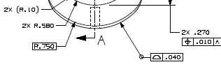
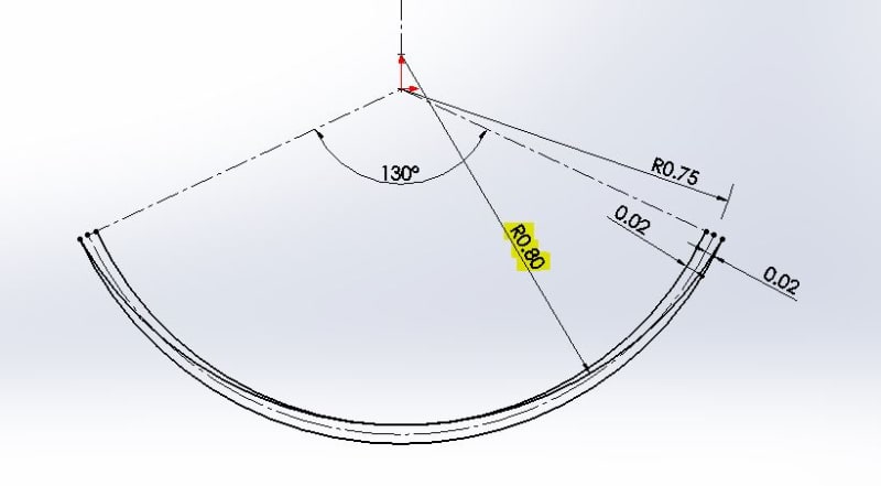
To demonstrate that .750 basic and profile within .040 is not quite the same as .750+/_ .020, I would recommend to draw one curve/ semicircle with a radii of .750 then offset this radii .020 outside and .020 inside in the same way profile definition is stated per its definition. This will create two boundaries, one outside and one inside.

Then, if you try to fit some curves between those two boundaries you just created above, you will see that you are ABLE to add curves whose radii are way outside plus/minus radii specification .730 - .770.

I don't have CAD available now, so would be nice for someone to confirm (or reject) my statements above. I think I read it on this forum (or maybe other forums).

No hard feelings if I am wrong.
 
Status
Not open for further replies.
Back
Top