Continue to Site

Eng-Tips is the largest engineering community on the Internet

Intelligent Work Forums for Engineering Professionals

  • Congratulations SSS148 on being selected by the Eng-Tips community for having the most helpful posts in the forums last week. Way to Go!

Radius vs. Diameter when Dimensioning Semi-Circle 2

Status
Not open for further replies.

Mitchell37

Mechanical
Aug 24, 2020
5
Hello,

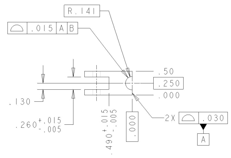
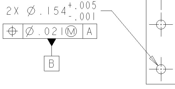
I am struggling with myself to determine if this feature should be called out as a diameter or as a radius. The feature is a hole which is in-line with the edge of the part, making it a semi-circle. I have attempted to attach 2 dimensioning schemes that I am caught between. I can't seem to find any standard to confirm which method is right (diameter callout or radius callout). So, my question to you is what is the correct way to callout the semi-circle feature? Is it a diameter? Is it a radius?

Diameter Callout

Radius Callout

Thanks
 
 https://files.engineering.com/getfile.aspx?folder=d19006f8-b466-439c-9fc6-27388d5b63da&file=Diameter_Callout.png
Replies continue below

Recommended for you

What standard are you adhering to? Is it ASME or ISO, and what version?

Whether its called out as a radius or diameter makes little difference to a profile tolerance, as long as its basic, though radius might be the most intuitive in this case.

Applying a position tolerance to a radius dimension, regardless of what the actual feature looks like, is questionable at best. I'm not sure if theres anything which strictly prohibits it, but a FOS must contain opposed points* so it should be attached to the dimension, or control (ie: a profile tolerance on an iFOS like Y14.5-2009 fig 8-24) which suggests opposed points. A radius does not inherently imply this.

Personally for such a feature profile would be the ideal control. There have been many discussions here about alternate dimension/control schemes for 180deg semi-circles, a quick search will bring up several, but profile is by far the most robust. If you were to change the directly toleranced dimension to a diameter and apply a position tolerance, you could be technically correct as it can technically contain a UAME (has opposed points) but you should know the limitations - any deviation in the intersecting surface can result in a semi-circle of less than 180deg and an unstable UAME. Even at exactly 180deg the containment of a UAME by a real as-produced surface may still be unstable, especially if the flexibility of the part and associated gauging elements are considered.

*actuall the delineation is a little more nuanced than that (rFOS is defined by specific shapes ie: cylindrical/circular element which are associated with diameters or iFOS can contain/be contained by an AME) however "opposed points" is the most simple way to intuitively explain it in a general sense.
 
An assumption you have a 3 place tolerance callout on the dwg format.
This tol will vary between R and Dia, larger for R.
Pick which one works with your design.

ctopher, CSWP
SolidWorks '17
ctophers home
SolidWorks Legion
 
chez311 said:
What standard are you adhering to? Is it ASME or ISO, and what version?

Whether its called out as a radius or diameter makes little difference to a profile tolerance, as long as its basic, though radius might be the most intuitive in this case.

Applying a position tolerance to a radius dimension, regardless of what the actual feature looks like, is questionable at best. I'm not sure if theres anything which strictly prohibits it, but a FOS must contain opposed points* so it should be attached to the dimension, or control (ie: a profile tolerance on an iFOS like Y14.5-2009 fig 8-24) which suggests opposed points. A radius does not inherently imply this.

Personally for such a feature profile would be the ideal control. There have been many discussions here about alternate dimension/control schemes for 180deg semi-circles, a quick search will bring up several, but profile is by far the most robust. If you were to change the directly toleranced dimension to a diameter and apply a position tolerance, you could be technically correct as it can technically contain a UAME (has opposed points) but you should know the limitations - any deviation in the intersecting surface can result in a semi-circle of less than 180deg and an unstable UAME. Even at exactly 180deg the containment of a UAME by a real as-produced surface may still be unstable, especially if the flexibility of the part and associated gauging elements are considered.

*actuall the delineation is a little more nuanced than that (rFOS is defined by specific shapes ie: cylindrical/circular element which are associated with diameters or iFOS can contain/be contained by an AME) however "opposed points" is the most simple way to intuitively explain it in a general sense.

I work with ASME Y14.5. This was an excellent response and helped support my theories with profile vs. position. I'm newer to the fourm and I went through several threads trying to find an answer like yours. I believe I used the wrong terminology to search with and that's how I ended up here.

Thank you again for the response.
 
Mitchell37,

I don't think it matters. I can interpret a radius or a diameter. Do you think the fabricator will drill the hole and then cut the part to length, mill into the feature with an 9/32[ ]mill, or will they track around the radius with a smaller cutter?

I do question the basic dimension. Either it needs an feature of size tolerance, or the feature control frame could contain a profile tolerance. If you specify the profile, you can change between the diameter and radius without affecting your tolerance. A positional tolerance is not very inspectable when applied to a radius feature, regardless of how you called it up.

--
JHG
 
Mitchell37,

Glad my explanation made sense, happy to help. I looked through and also had difficulty finding the discussions - I remember having these conversations but for some reason they're not coming up in a search. The one that I did find which included a sample of a tec-ease tip was (
 
drawoh said:
Mitchell37,

I don't think it matters. I can interpret a radius or a diameter. Do you think the fabricator will drill the hole and then cut the part to length, mill into the feature with an 9/32 mill, or will they track around the radius with a smaller cutter?

I do question the basic dimension. Either it needs an feature of size tolerance, or the feature control frame could contain a profile tolerance. If you specify the profile, you can change between the diameter and radius without affecting your tolerance. A positional tolerance is not very inspectable when applied to a radius feature, regardless of how you called it up.

Which dimensioning scheme and what basic dim are you referring to?
 
Mitchell37,
I believe drawoh refers to the basic diameter at the dimensioning scheme that includes the position tolerance.

Also, both your sketches feature a basic .250 locating dimension - you are missing a datum to make it meaningful. Additionally, If there is Basic .250 as shown the .000 should also be basic.
 
Mitchell37,

As Burunduk has noted, the [⌀].281 dimension is shown as basic on your drawing. You need to control the size of this feature somehow.

--
JHG
 
Revised_Dimensions_kpwon1.jpg

Datum_B_b8sysb.jpg


This is where I ended after reading through this thread. The intention is to drill the hole through and then mill excess material down to create the semi-circle feature.

Datum B is two bolt holes used for assembling this component. Datum B establishes an axis and two planes to fully define my DRF and constrain the 6 degrees of freedom on the part when in conjunction with datum A.

The help and opinions are greatly appreciated! Thank you all. I am a young, growing engineer so bear with me..
 
Mitchell37,

Don't tell the fabricator how to do his job.

If that end face, datum [ ]A, is the primary datum feature, it ought to be done first, and everything else fixtured to it. The 0.00[ ]feature should not be basic. The profile tolerance you have applied to the feature is legal as per ASME[ ]Y14.5, but all you are controlling is flatness. Your fabricators will trust you more if you call up flatness.

--
JHG
 
drawoh,
Seems like Mitchell37 tries to employ Rectangular Coordinate Dimensioning Without Dimension Lines (As in fig. 1-50 in Y14.5-2009), but I think that making one dimension basic (.250) and the other coordinates non-basic (.000 and .50) is not correct. .000 basic could represent a base line, hence my suggestion.

But this type of dimensioning would make sense if datum feature B was the bottom face, which doesn't seem to be the case here. I don't understand where datum feature B is on the part as shown in the original view.

Also, drawoh - the profile tolerance on datum feature A is needed to control coplanarity if it is to be used as a single datum feature that utilizes both surfaces. Not sure I follow why you suggest flatness instead.
 
Status
Not open for further replies.

Part and Inventory Search

Sponsor