Continue to Site

Eng-Tips is the largest engineering community on the Internet

Intelligent Work Forums for Engineering Professionals

  • Congratulations KootK on being selected by the Eng-Tips community for having the most helpful posts in the forums last week. Way to Go!

Rating a Shear Connection using Allowable Stress 2

Status
Not open for further replies.

AK4S

Structural
Jan 2, 2015
98
Need some advice from any Bridge Rating Engineers.
I am rating an existing bridge (4 Simple spans,rolled steel beams with a noncomposite concrete deck) which has a Shear connection (Web Splice plate only. No splice connection on the flanges) on the beams of one of the interior spans. It looks to be a construction error where the pier was off by few feet, so they added a Shear connection on the original beam length to make it work. The splice is located close to the support (3ft away from support on a 74ft beam span), so the behavior can be assumed to be as 2-Span continuous with a hinge at the splice location.
Untitled_lhboji.jpg


I analyzed and rated the beams using AASHTOWare. The Shear Forces at the hinge for various load conditions can be obtained from AASHTOWare and used to rate this Shear connection for:
► Connection Bolts in Shear and Bearing
► Flexural Yielding and Flexural Rupture of the Connection Plate due to the Eccentric moment from the applied Shear force
► Shear Yielding and Shear Rupture of the Connection Plate
► Block Shear and Tension Fracture of the Connection Plate

I could not find any examples using AASHTO Std Specs for Highway Bridges or in the MBE(Manual for Bridge Evaluation) to evaluate this connection using Allowable Stress (ASR).
Any suggestions or examples I could refer? I can get the necessary allowable stresses for plate and bolts from the MBE but not sure about the equations to be used to evaluate stresses due to the loads.

The bridge was originally designed using ASD and per State DOT's guideline we need to rate it using Allowable Stress.

Alternatively (Not the preferred option to avoid mixing different code provisions) I am familiar with evaluating the connection using AISC provisions, however I am not sure on how to consider the effects of mixing load factors and varying allowable stresses when mixing the two codes for evaluation. Any suggestions?
 
Replies continue below

Recommended for you

I would be very cautious about considering the splice a shear only connection, since it will carry moment. Under the right conditions, it will form a plastic hinge, which will limit the moment in the connection. However, if the shear capacity of the bolts is not greater than the force necessary to fully yield the splice plates, the bolts could shear before the plastic hinge forms. If the bolts aren't fully tensioned, the net section of the splice plates could also fracture below the hinging moment. Either of these conditions could result in a brittle failure at the splice.

If you can't be confident that the splice plates will fully yield without fracturing or shearing the bolts, the load carrying capacity of the bridge may be limited by the splice capacity for combined moment and shear.

Rod Smith, P.E., The artist formerly known as HotRod10
 
My thought, if this was a construction error, then I would suspect that your negative flexure rating over the 3rd support would govern as the bottom flange was never designed for that type of compression. The fact that it is non-composite doesn't help any.

Any chance you can check the connection per LRFR? If the load rating is above 1.0 (or does not govern) I would try to have a quick dialogue with the Project Engineer to see if they could provide an exception. I would think this would not be an issue since it meets today's standards.
 
After rereading your post and seeing that the splice is only 3ft away from the support, I tend to agree with Rod that the true behavior of that connection will surely transfer some moment and amplify the bolt shear.

One suggestion. Try modeling spans 2 and 3 as a continuous beam element but apply the appropriate flexural stiffness of the bridge at that point. I.E. only 2 web splice plates with no flanges. This will create a soft point in the model but will not be a true hinge. You can check your capacity then based on the shear and moments that you obtain from this model.
 
Thank you for your thoughts.
I did an initial check using AISC provisions (with MBE allowable stresses though) and the Shear Yielding of the plate seems to govern. This led me to believe, that the plate yields before the bolts fail.
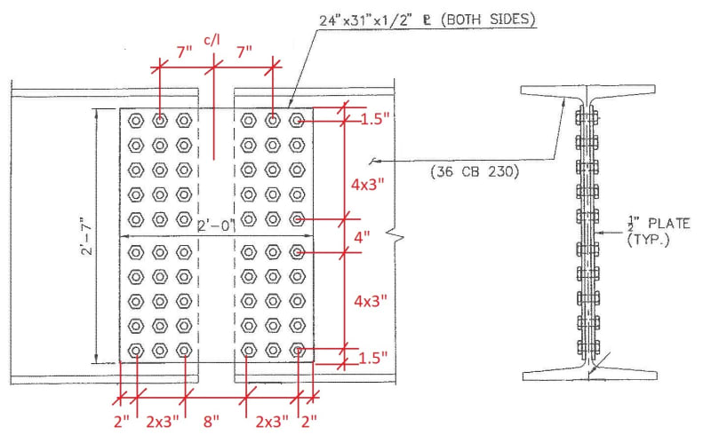
Below is a sketch of the connection:
Web_Splice_Sketch_d9ijur.jpg


The plate does see in-plane moment due to the eccentric location of the shear load, but with a gap at the flanges will the connection transmit moment from the beam? or would it allow the beam to rotate instead (connection acts a hinge)?
 
The in-plane moment due to the eccentric bolt location is understandable. It's really tough to say how much moment is actually being transmitted through that connection. It will not be a true pin nor will it be truly fixed. This is why I suggested introducing an upper bound maximum level of stiffness that you might expect to see at that location and see if that relieves some of your moment. There must be some level of pretension on those bolts, so at the very least you are getting some moment transfer through friction. If the joint has rotated slightly and the bolts are now bearing at the edges of the hole, you will again engage some flexural rigidity from that. Do you have any close up photos of the joint, as it is today? I would like to see if there is any noticeable signs of distress (probably hard to see) or any rotation? Has this bridge been in operation since the ~1940's and carries regular overweight trucks? Or is it already load-posted?

I tried finding the yield strength of a CB wide flange beam but couldn't seem to find it. What material properties are you using for the splice plate and beam?

Do the splice plates use a considerably lower grade steel than the beam? I'm trying to figure out how web yielding controls.

I'm assuming webs of beam are unstiffened and Cv = 1.0.

Area of web of the beam = 26.9 in2
Area of splice plates = 31.0 in2

 
There will be moment due to bending of the girder and from the eccentricity of the shear. The eccentricity is the distance from the center of the splice to the center of the bolt group. The total force on a bolt (and bearing on the edge of the bolt hole) is the sum of the vertical load from shear and the force due to the moments, both the applied moment in the girder and the moment due to eccentricity.

Rod Smith, P.E., The artist formerly known as HotRod10
 
There is a limit amount of moment to maintain conformance of displacement between two linked segments, but it is conventionally assumed pinned/hinged for analysis and design, except for the design of the link elements (plates and bolts).

OP said:
It looks to be a construction error

I am curios about it. Was it an makeup for error, or design on purpose? Seems many bridges have similar feature.
 
@STrctPono: The bridge has not been posted and has been carrying usual suburban traffic for the last 50+ years.
I will explore your suggestion to model the 2 continuous span with the flexural stiffness of the web splice plates at the connection and obtain shear and moment to rate the connection.
From my initial analysis of the connection using 33ksi plates(AISC provisions for typ. shear connection and MBE allowable stresses),the Shear Yielding of the plate seems to govern compared to the bolt capacity. The splice plates have reduced thickness due to corrosion (the joint in the deck above the splice leaks)
 
@BridgeSmith:Yes, I would need to include the portion of moment in the girder to my analysis of the connection. Modeling per STrctPono's suggestion should give me the shear and moment values.

Still looking at suggestions on how to Rate the connection using allowable stress per AASHTO provisions.
 
@retired13:not sure if I understood the response correctly "but it is conventionally assumed pinned/hinged for analysis and design, except for the design of the link elements (plates and bolts)." How are the link elements conventionally designed in this case?


In my case, this splice condition did not look like something designed on purpose. All other spans are simple span 74ft. Only one pier is off by 3ft. Also, the original bridge plans did not show this splice connection.
 
Instead of one continue piece of beam element, now you have two beam elements connected by a pin, at which, M=0. Thus you analysis the beam and design the two beam segments accordingly (M=0 at link). I don't know what you don't understand about.
 
@retired13: I am talking about the design of the connection(web splice plate and bolts)
 
It's also not a pinned connection, retired13. Modeling the girder with a pinned/hinged connection is the conservative approach for the girder, but certainly not for the connection, which is very likely to be the controlling feature for the load rating.

I also agree with STrctPono's approach of modeling it in AASHTOware (BRASS-Girder) with a short section (as short as it will let you) that is just the splice plates as the 'girder section'. With that you will get moments, shears and ratings for whatever live load combinations you input.

After that, you'll need to check the splice components (bolts, bearing at the bolt holes in the splice plates and web, net section fracture of the splice plates, net section fracture of the web) for the moment, shear, and moment due to the eccentricity of the shear. You should be able to use BRASS-Splice to verify your checks by entering tiny flange areas. If you need some help with that, let me know what version of Splice you're using, and I can probably help you. Versions 5.0 and up are using the new design method in the 8th Ed. of the LRFD spec, which is radically different than the previous method. I was deeply involved in the development and beta testing of the older versions of Splice, but I was not really involved with the update to Version 5.0 and beyond.


Rod Smith, P.E., The artist formerly known as HotRod10
 
@BridgeSmith: Thank you for your inputs.

Regarding the rating of the Splice Components: I am not familiar with the BRASS-Splice module. For the Splice Rating module in AASHTOWare, I found the attached note which kind of says that one cannot use thin plates as a work around for the lack of flange plates (when using AASHTOWare).
 
 https://files.engineering.com/getfile.aspx?folder=f9a458fc-c5c6-4a8c-8b70-edb8d4c842ce&file=AASHTOWare_Splice_Check_Inconsistencies.jpg
I guess I never tried one without flanges. It's very possible the calculated web portion of the design moment, per the equations in the spec, would not be the full moment on the girder. Since the spec. equations, and therefore the programmed equations, don't consider a configuration without flange splices, you may not be able to use the program.

If your sketch is to scale, bearing at the web holes (bolts tearing out of the web) could be a controlling failure mode once you apply the moments to the connection. Calculating the polar moment of inertia of each bolt group (the bolts on each side of the splice) will be a PITB with the variation in spacing. The program wouldn't have given correct answers because of that, either, since it only handles regular 3"x3" or 4"x4" bolt spacing.

Rod Smith, P.E., The artist formerly known as HotRod10
 
retired13 said:
There is a limit amount of moment to maintain conformance of displacement between two linked segments,

I agree the language is unclear, but specifically I meant there is moment capacity in the connection, but limited to the strength of the connection plate and bolts. However, this moment has nothing to do with the design of the connected members, which are to be analyzed and designed by conventional method assuming the connection is a "perfect pin" - zero moment. Sorry for the ambiguity of my writing.
 
The splice is definitely not a design error - that's so called Gerber beam, and the splice is located at or near zero DL moment. Design assumption was that only shear will be carried, with the connection plates forming a plastic hinge.
 
You can always just check all the failure modes by hand. You are already getting a moment in the connection due to the shear coupled with the eccentric bolt arrangement so it's pretty straightforward to add the additional moment you get from the beam analysis.

BRASS Splice would be a nice tool to check your rating, however, if it can handle a web splice only design. You might want to send Brian a message over at BridgeTech. Explain that you are looking to purchase the program but you want to know if it can handle a web splice only design.

I am unfamiliar with AASHTOWare. I would assume that the program is a true structural analysis program and not just one that is based on influence diagrams. Therefore, to verify that AASHTOWare is handling your stiffness reduction correctly, you may want to run a verifying beam analysis in whatever structural engineering or FEA program you have in the office to check the results. I do this exact same thing when load rating haunched concrete girders for the same reasons.

Again, I have nothing helpful to offer regarding your ASD/ASR dilemma.
 
wiktor said:
the splice is located at or near zero DL moment

Contraflexure at 3ft away from the support on a 74ft span? I don't think so
 
Status
Not open for further replies.

Part and Inventory Search

Sponsor