Continue to Site

Eng-Tips is the largest engineering community on the Internet

Intelligent Work Forums for Engineering Professionals

  • Congratulations KootK on being selected by the Eng-Tips community for having the most helpful posts in the forums last week. Way to Go!

RBE3 singularity problem

Status
Not open for further replies.

matty90

New member
Jul 23, 2021
7
Hello everyone!
This is my first post in this forum so I hope I'm not breaking any rules!
I have already read some threads on this kind of problem but somehow I couldn't find what I was looking for.
I have decided to use RBE3 to apply some loads to a beam. Singularity fatal error does occur, though I think I have selected the "right" DOFs in both the dependent and independent terms of the RBE3. In fact, all translations that define rigid body motion have been activated on the independent node, as well as all possible DOFs related to moments that should develop.
The model is attached to this post. It is a cantilever beam loaded on its tip using the RBE3.
Thank you in advance for your attention. This forum has provided me some insights quite some times.

Greetings!
 
 https://files.engineering.com/getfile.aspx?folder=63596e7e-2b2d-4e86-898c-6f552b04427b&file=test_rbe3.bdf
Replies continue below

Recommended for you

Which dof and at which nodes are you failing?

Only looked at the Bdf briefly, but it seems node 3 is only connected to the rest of the model by 1dof on the rbe3. I think that's you're problem here, the other dof on node 3 are unconstrained, hence you should get a pivot ratio error on dof 2-6 for node 3.

As you are connecting only two nodes, and there are no other constraints on node 3, you would be best activating all dof on the rbe for nodes 2 and 3. Or use an spc for the remaining unconstrained dof on node 3. Because of this, the rbe3 will do nothing special in this particular application.
Typically I would use an rbe3 with >= 2 independent nodes (with dof 123) and all 6dof on the dependent node.
 
Hi guys!
Thank you for your reply!

@FEA way --> Thank you for your message. Unfortunately the thread you posted was exactly the same one I had tried before to no avail!
Here's all I can get on the issue from NASTRAN .f06 file:

USER FATAL MESSAGE 2038 (RBE3S)
RBE3 ELEMENT 2 IS SINGULAR.
USER ACTION: ADD MORE DOFS TO THE CONNECTED POINTS TO INSURE THAT THEY CAN CONSTRAIN ALL 6 RIGID BODY MODES
OF THE ELEMENT.

@Ng2020 --> Answer to you point by point:
"I think that's you're problem here, the other dof on node 3 are unconstrained, hence you should get a pivot ratio error on dof 2-6 for node 3" --> Thank you, I shall think about it. In NASTRAN
linear user guide RBE3 sample problem the RBE3 only uses a single DOF related to the direction of the load. Hence I thought it was ok.
I know that this is not your tipical everyday problem but I had to understand in detail how RBE3 works, in order to use it correctly on further applications. This was the simplest case I
could think of!

 
No problems.
Do they use autospc in the example perhaps?
If you're interested in an abstract mathematical description, from memory there's a good one in the femap nastran technical guide.
 
Hi!
Answering by points:

[ul]
[li]Do they use autospc in the example perhaps? --> Nope![/li]
[li]If you're interested in an abstract mathematical description... --> Thank you for the insight! I looked on it but I also managed to get something good from this doc Indeed, I thought I understood it correctly but it seems that something's missing from my picture![/li]
[li]Tried by using all rotations (Hence all six DOFs) on the INDEPENDENT node. It runs and provides expected results. Which confuses me actually because no rotations occur around axis 4 for node 3 and so DOF 4 should not be used on it. But as already said, if I do not include it in the INDEPENDENT node DOF list of the RBE3, I get some error messages. Maybe some very small (E-13 order error occur?)[/li]
[/ul]
 
That's how linear static FEMs work, you can't leave dof's unconstrained, otherwise you have a mechanism.

One way to think of the rbe3 is that it's an interpolation element. If you have only 1 dependent node connected to the independent node, there's nothing to interpolate.

I'd suggest a non-trivial example instead, such as pressure loading on a membrane. Connect multiple plate nodes
(dof 123) to an independent node (dof1-6) located at the centre of pressure.

Did you have a specific application in mind?

Edit: that's a pretty comprehensive guide to the rbe3 that you've linked.
 
Thank you for your reply.
I think I have managed to come up with some sort of explanation. Basically is a long explanation of what you said above.
Arranged in the following points:

[ul]
[li]As explained in the doc linked in my previous message, RBE3 element imposes a rigid body motion on the DEPENDENT node. Such motion is driven by the INDEPENDENT node(s) as if they were a rigid body.[/li]
[li]A passage from the NASTRAN linear user guide section relative to the RBE3 element explains that the RBE3 itself must be able to behave like an isolated body itself. To define such motion in space you need to define both 3 translations and 3 rotations (6 DOFs). In fact, each node in linear FEM has 6 DOFs (aside from solid element ones I think).[/li]
[li]In rigid body motion if you happen to know at least 2 pure translations vectors from at least 2 different points, you can find the pure rotation vector of the body they belong to. Hence if RBE3 has MORE than 1 INDEPENDENT node, rotations should be avoided (NASTRAN linear user guide suggests to do so). Otherwise, in case of a SINGLE INDEPENDENT node, it is not possible to know the rotations of the RBE3 element unless they are specified.[/li]
[li]What confused me and lead me to ask for help was the fact that in all RBE3 element explanations the DOFs (dependent and independent) selection is based on the forces/moments one wants to transmit with the RBE3 itself. Balance was the focus.
Instead, what should be noted (imho) is that since RBE3 is treated as a particular "element" , both kinematic and equilibrium equations must hold and they cannot be tied to one another through a stiffness matrix. So rigid body force/moments balance and motion laws come into play and must be accounted for when defining the RBE3 INDEPENDENT nodes.[/li]
[/ul]

@Ng2020 --> To answer your question: originally I was trying to simulate a "rigid" 3D truss structure. I could use super rigid BAR elements but I thought I might get the same results through proper RBE3 usage!
Yes, the team who did that site should be all made saints!

I hope this whole discussion helps to clarify and use this FE tool in a more conscious way.
If anybody thinks I might have missed the point just tell me so!
Thank you for the attention so far and sorry for the long reply!
 
Dear Matty,
In fact, your RBE3 is singular, is the message of nastran, you need to constraint ALL your DOF in the INDEPENDENT node to get working.

The most common user error in RBE3 element specification results from placing 4, 5, or 6 in the Ci (independent DOF) field in addition to the translation components. The rotations of the dependent point are fully defined by the translational motion of the independent points. The ability to input 4, 5, or 6 in the Ci field is only for special applications, such as when all of the connected points are colinear.

In summary, the intended use of the RBE3 element is to transmit forces and moments from a reference point to several non-colinear points. The rotation components 4, 5, and 6 should be placed in the Ci field only for special cases, such as when the independent points are colinear.

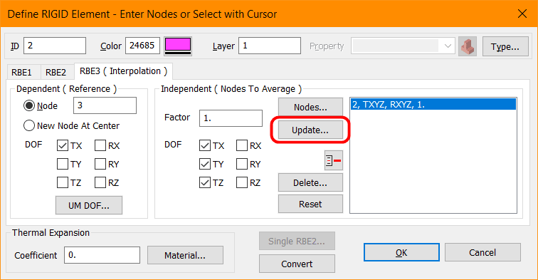
rbe3-error-1_dzbg3j.png

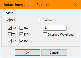
rbe3-error-2_hjmza6.png


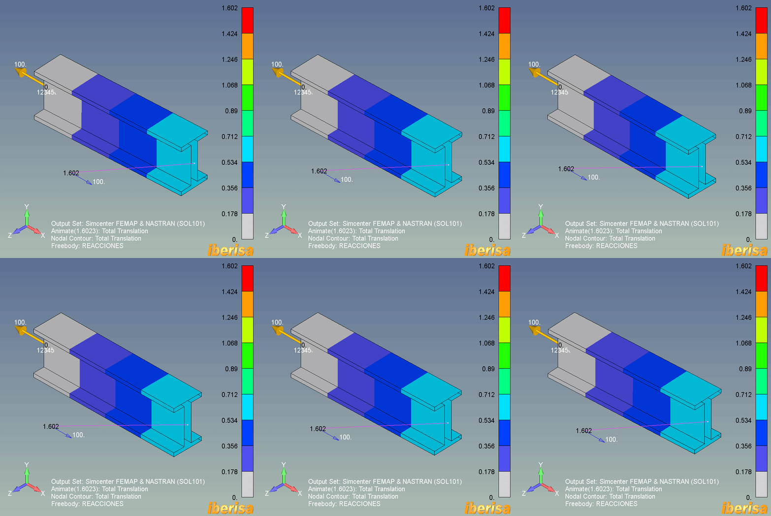
This way you will arrive to a solution:

rbe3-error-animated_g1htnx.gif


Best regards,
Blas.

~~~~~~~~~~~~~~~~~~~~~~
Blas Molero Hidalgo
Ingeniero Industrial
Director

IBERISA
48004 BILBAO (SPAIN)
WEB: Blog de FEMAP & NX Nastran:
 
@ BlasMolero
Thank you for your suggestion!!
It is correct indeed!
 
Status
Not open for further replies.

Part and Inventory Search

Sponsor