Continue to Site

Eng-Tips is the largest engineering community on the Internet

Intelligent Work Forums for Engineering Professionals

  • Congratulations GregLocock on being selected by the Eng-Tips community for having the most helpful posts in the forums last week. Way to Go!

RC Beam with unusual geometry from 1929

Status
Not open for further replies.

ThomasGeoghegan

Structural
Sep 3, 2021
5
I'm working on the renovation of a reinforced concrete building from 1929.
I have the original drawings, and have come across an unusual concrete beam.

Below is an imgur link, because I couldn't get the attachements to work:

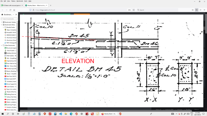
Image 01_Beam Detail shows a detail view of the beam.
The beam is nonprismatic, 16"x34" at one end, and 18"x28" at the other.
There are other irregularities found in the detail as well.
All other beams are rectilinear, with a section that was rectangular, T-Shaped, or L-shaped.

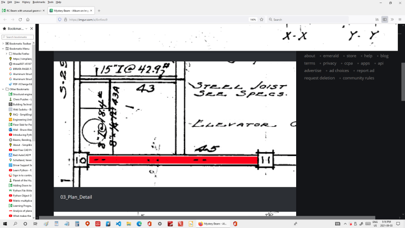
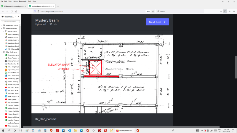
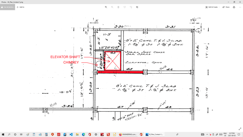
Images 02_Plan Context and 03_Plan_Detail show the beam's location. It is a roof beam, adjacent to an elevator shaft and a chimney, below a penthouse.

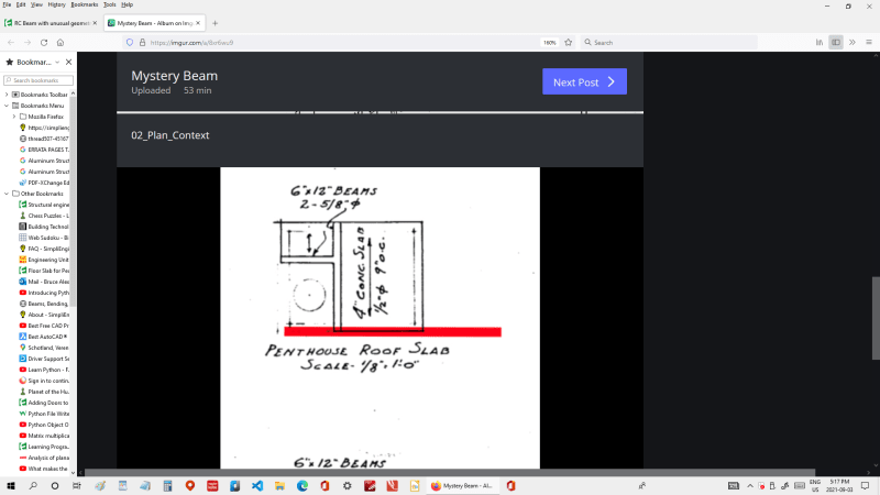
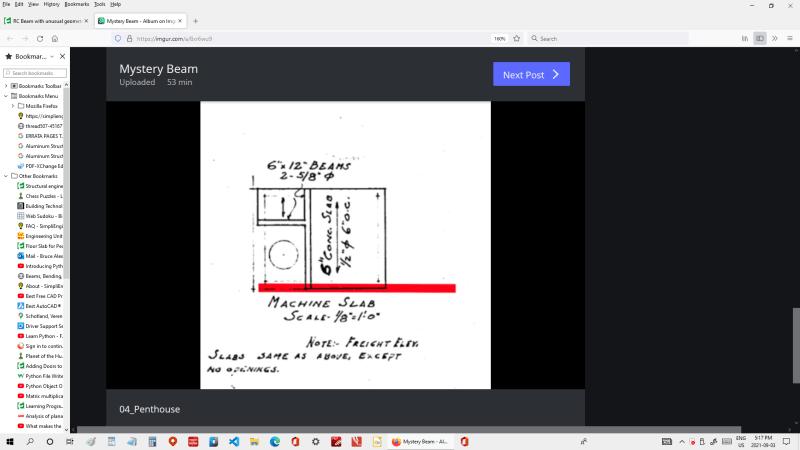
Image 04_Penthouse shows the penthouse plans. The mystery beam's location is highlighted in red. It would be directly below the penthouse.

Neither I nor any co-workers can figure out the advantage of this utterly bizarre 90-year old beam.

The drawings we have are fairly sparse. There are no specifications or shop drawings available.
The drawings show no other beam designed in this level of detail. All other beams are shown diagrammatically on the plans, and their dimensions are shown in a beam schedule.
I was able to make a site visit, but the beam is hidden inside of some walls that would have to be demolished to get a good look.
From what I was able to see through the drop ceiling, the beam was built as a rectangle

The renovation does not call for the beam to be removed or modified, so figuring out the mystery is not mission-critical.

That said, I am very curious and am wondering if anyone here can guess what this weird beam is for.
Drafting practice? Cruel joke on the Contractor? Thank you for any theories.

 
Replies continue below

Recommended for you

Something to do with drainage? Keeping water away from the lift shaft somehow?
 
The increase in beam section coincides with the cutout for the lift shaft/chimney.
Are other floors similar? I.e. Is it used to redistribute load around the slab cutout?
 
I've been having trouble with the Image button too, but here goes:

Screenshot_13_y4erdg.png


Screenshot_14_pqg2un.png


Screenshot_15_enc7xo.png


Screenshot_16_dnjnet.png


Screenshot_17_qfl8su.png


BA
 
Drainage was my first thought, while keeping the soffit level, but why change the width?

Screenshot_18_umef9f.png


BA
 

gusmurr (Structural)

Something to do with drainage? Keeping water away from the lift shaft somehow?
---
The adjacency to the shaft does make this beam unique.
However:
- There is another area of the roof with a slope. There, the entire roof slab and beam/joist system are sloped
- A plain concrete built-up slope would be easier to make than a slope integral to a structural member.
- The beam does not slope away from the shaft
- There are other openings on the roof (skylights) with no special sloping

The mystery continues...
 
Where does the width change? You kind of imply a width taper, but I don't think that's true at all.

Seems to me it's more likely you get an abrupt change in the width at some point, likely coinciding with the beam coming in that trims the elevator penetration?

Note how the centreline of the column 10 is off centre on the beam on the section, but it isn't shown the same on the plan (I believe the plan isn't quite right here), and at the elevator you lose 2" of width on the shaft side as implied on the section. Seems perfectly normal to me.

It would be very odd to have the width taper. The only reason I could think of was to allow the beam bars to spread out to get between the column cage or something, but then wouldn't you have the same thing going on at each end given columns appear to be similar size (but may have quite different reinforcement layouts).

Overall, beam seems 2" narrower on one side as you get to the lift shaft, which seems relatively normal change to maybe accommodate the shaft.

 
Ng2020 (Aerospace)

The increase in beam section coincides with the cutout for the lift shaft/chimney.
Are other floors similar? I.e. Is it used to redistribute load around the slab cutout?
-------
The chimney does seem like it might be related.

However:
At lower floors, there are beams in this location. These beams are all L-Shaped or rectilinear.
If a beam of larger section might have been needed, but they chose an unbelievably labor-intensive way to to do it. An 18"x34" beam (the larger dimension of each end) would have been way easier to build than the complicated non-prismatic beam.
 
BAretired (Structural)

Drainage was my first thought, while keeping the soffit level, but why change the width?
------
- This is the part that really bugs me.

Also, thank you for posting all the images.
 
Agent666 (Structural)
"Where does the width change? You kind of imply a width taper, but I don't think that's true at all. Seems to me it's more likely you get an abrupt change in the width at some point, likely coinciding with the beam coming in that trims the elevator penetration?" | Best, simplest theory so far. IF the beam does change in width abruptly, there cannot be continuous rebar in the wider part, but i suppose the width change could just be to fit with the shafts.

"Note how the centreline of the column 10 is off centre on the beam on the section, but it isn't shown the same on the plan (I believe the plan isn't quite right here), and at the elevator you lose 2" of width on the shaft side as implied on the section. Seems perfectly normal to me." || The plan is definitely more diagrammatic than literal, so this might be the case.

"It would be very odd to have the width taper. The only reason I could think of was to allow the beam bars to spread out to get between the column cage or something, but then wouldn't you have the same thing going on at each end given columns appear to be similar size (but may have quite different reinforcement layouts)."|| The columns to have the same reinforcing.

"Overall, beam seems 2" narrower on one side as you get to the lift shaft, which seems relatively normal change to maybe accommodate the shaft." | Abrupt change in width seems to be the best theory. There are however other beams at this location at lower levels of the building that do have abrupt width changes that did not get special beam details like this "Detail 45". I am surprised that only this beam got its own detail.
 
Status
Not open for further replies.

Part and Inventory Search

Sponsor