Continue to Site

Eng-Tips is the largest engineering community on the Internet

Intelligent Work Forums for Engineering Professionals

  • Congratulations waross on being selected by the Eng-Tips community for having the most helpful posts in the forums last week. Way to Go!

RC Design - Octagonal Footing with Piles

FreshGenZSE

Structural
Oct 30, 2024
5
Hello Engineers,
First time posting and keen to get some design advices. Please see query as below.

Question:
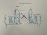
I have an octagonal footing foundation design for wind turbines. What is the rationale of not having the stirrups (light blue) continuing into the “x” region marked in purple shown in the attached cross-section, 3 m thick?

For illustration purpose, please see the sketch below.
IMG_9725.jpeg

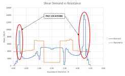
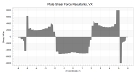
The governing shear force diagram is as below.
IMG_9721.png

I say to provide stirrups myself but open to discussion as I may be overly conservative! Note that the shear demand is significantly larger than the concrete strength and the wind turbine tower is hollow.

Reason(s):
  1. I have seen similar details in different projects with only mass concrete in the same region. I pointed it out to my manager and colleagues. They do believe it should be provided, but have no answer to my query so far.
  2. I am uncomfortable to make the additional depth assumption as the tower is a hollow section. I am also recommended the same as it could be a risky call.
  3. I have attempted to use strut-and-tie to justify that diagonal strut is viable alone. I resolved the overturning moment into axial tension and compression at the bolt connection, but found it impossible to have no tie in the region while having a model that is structurally stable!
For your information, I am a junior engineer with 2 year of working experience, and pretty unconfident with my own designs. If I have uttered something wrong, please do correct me so that I can learn!

Thanks in advance.
 
Replies continue below

Recommended for you

To be sure that I am understanding the foundation, the octagonal pad is supported by piles, I'm guessing at least 4 piles around the perimeter?

How much deeper would the middle section of the footing need to be to avoid the need for stirrups?

I would guess that they may be sized so that stirrups aren't needed in the middle portion, and the stirrups near the anchor bolts are only there to provide tension breakout reinforcement.

Any chance you are looking at the worst 1m section of concrete where the stresses are very high, but not looking at the section as a whole?
For example, when designing two way slabs we don't design the column strips for the stresses in the middle foot of the strip where the stresses are the highest, we design it for the total loads across the whole strip width and use the whole strip width to resist the loads.
That will often happen with FEA. If you design a simple spread footing using FEA and compare it to a hand calc, you will find that FEA requires much more rebar because of the higher stresses concentrated near the center of the footing while the hand calcs assume that the moments and shears are resisted by the entire width of the footing.
 
I've done octagonal pedestals and foundations for vertical vessels in industrial / petrochemical facilities. And, I was going to say something similar.

We never provided shear reinforcing for these slabs at all. We would put some horizontal ties in the pedestal. Most of the concern was usually related to the anchor rods where we often had reinforcement to make sure our anchors had sufficient pull out (or shear) strength.

That being said, I'm guessing that wind turbines might be a little different. There is more of a dynamic load associated with it.
 
Hi HDStructural, first all of, thanks for your comment and time.
To be sure that I am understanding the foundation, the octagonal pad is supported by piles, I'm guessing at least 4 piles around the perimeter?
Yes, there are 8 piles, with one located near each face of the octagonal foundation.

How much deeper would the middle section of the footing need to be to avoid the need for stirrups?
3 m is the maximum thickness I can have as it will be hard to achieve the minimum longitudinal reinforcement requirements without paying extra for a larger bar diameter. For your information, I have around 5300 kN/m shear demand, while a 3 m thick section gives 1300 kN/m. If I go 5300 / (1300/3) for an approximation, it will give me a section of 12.25 m thick.

Any chance you are looking at the worst 1m section of concrete where the stresses are very high, but not looking at the section as a whole?
Yes, the shear force diagram cuts through the worst section, parallel to the applied loads. I have provided the stirrups based on the shear force diagram. Please see the demand vs resistance plot for your information.

A graph with a red circle and blue linesDescription automatically generated
Note that they are all in per unit width. At the pedestal, there are no stirrups, only the concrete strength.

we design it for the total loads across the whole strip width and use the whole strip width to resist the loads.

To ensure I got the message right,
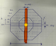
Take for example (sketch below, piles not showing for clarity), say that I am checking for the shear resistance at the yellow dot, I can mobilise the whole strip (highlighted in red) and check against the total shear demand of the whole strip width (i.e., adding demands above and below Section AA’ to the demand in Section AA’)?
A diagram of a hexagon with a yellow circle and linesDescription automatically generated
I note that the shear demand at the yellow dot is higher and decreases when travelling out from the centre before increasing again near piles.

If I follow the approach above, wouldn’t it mean that I overprovide at the outer region, but underprovide near the yellow dot? Utilising the whole strip width feels to me like distributing the shear resistance evenly throughout the strip, while the shear demand differs along the strip in consideration.

What is the reason to adopt a wider width rather than per unit width if the load may not distribute to the outer end of the strip?

Many thanks! :D
 
Hi JoshPlumSE, thanks for your comment and time. I have the following responses to your comments for clarification.

We never provided shear reinforcing for these slabs at all.
I assume there is sufficient shear strength from the concrete itself in the slab designs you mentioned, is that correct? Are there any other assumptions made to not provide the shear reinforcement in the pedestal?

That being said, I'm guessing that wind turbines might be a little different. There is more of a dynamic load associated with it.
Potentially. The foundation design load package provided by the supplier has considered the dynamic behaviour of the structure and present it in a load case for direct design purposes. The loads provided at modelled near top of the foundation face. I can’t tell if it differs much from vertical vessels besides the significant overturning moment of the wind turbine due to its height!

Many thanks!
 
FreshGenZSE,

If I follow the approach above, wouldn’t it mean that I overprovide at the outer region, but underprovide near the yellow dot? Utilising the whole strip width feels to me like distributing the shear resistance evenly throughout the strip, while the shear demand differs along the strip in consideration.

Yes, that is the idea. When designing standard pile caps or a spread footing, that is exactly what we are doing. Since concrete sections are so thick, they are able to distribute the load well, much better than a steel plate would. This is how it is done per the codes for various concrete applications.

Another example of this would be a masonry wall, with vertical rebar at 48" o.c. This wall is essentially designed in 4' sections even though portions of the wall have no rebar in it at all. An FEA model may show that the portions of the wall w/o rebar are highly overstressed while the portions with rebar have much more capacity than needed.

If you want to be more conservative, you could pick a strip width to design your sections for that is less than the total width of the pile cap, but I would argue that it should be at least 3 x depth of pile cap for a typical pile cap design (if not the full width as is standard practice). Based on your unique geometry however, maybe use a 5m or 6m strip width since that appears to be the width of your thicker section in the middle. See what the shear and moment demand/capacity are for the middle 5m of your section and you should find it much easier to get the design to work out.
 
I assume there is sufficient shear strength from the concrete itself in the slab designs you mentioned, is that correct? Are there any other assumptions made to not provide the shear reinforcement in the pedestal?
Yes, generally the slab thickness is based on punching shear. Flexural shear doesn't usually come into play. It's generally cheaper to increase thickness for a foundation than to get really complex with your reinforcement. At least in locations where concrete is cheap and labor is more expensive.

The foundation design load package provided by the supplier has considered the dynamic behaviour of the structure and present it in a load case for direct design purposes.
I was wondering if the vibration over long term could aggravate minor cracks that don't usually affect structural strength. Especially around the anchorage areas.
 
Hi HDStructural,
Yes, that is the idea.
Thanks for confirming the approach so that I have a clearer picture!

If you want to be more conservative, you could pick a strip width to design your sections for that is less than the total width of the pile cap, but I would argue that it should be at least 3 x depth of pile cap for a typical pile cap design (if not the full width as is standard practice). Based on your unique geometry however, maybe use a 5m or 6m strip width since that appears to be the width of your thicker section in the middle. See what the shear and moment demand/capacity are for the middle 5m of your section and you should find it much easier to get the design to work out.
Noted with thanks, it seems like I may be overly conservative to assume everything in per unit width when considering a beam action for such a deep section!

I will try to strike a balance between the full width and your suggestion of 3x depth of the pile cap. I have checked using the plinth itself and the shear capacity is sufficient!

However, I need to convince my senior regarding the findings. Therefore, I am looking into the shear stress distribution through an FEA model and see if there are any tell-tale signs regarding that to make a case!

Appreciate your time and input once again!
 
Hi JoshPlumSE,
Yes, generally the slab thickness is based on punching shear. Flexural shear doesn't usually come into play. It's generally cheaper to increase thickness for a foundation than to get really complex with your reinforcement. At least in locations where concrete is cheap and labor is more expensive.
Noted with thanks, I will keep that in mind. Perhaps someday I will encounter something similar!

I was wondering if the vibration over long term could aggravate minor cracks that don't usually affect structural strength. Especially around the anchorage areas.
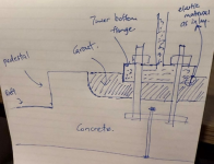
I see, I think I got the message wrong! You are right about the cracks aggravating around the anchorage areas. I believe there is a special grouting requirement at the interface due to high loads at the tower bottom specified by the turbine supplier. This may vary between turbines. There may be better options elsewhere, but the sketch below could be one of the many.

1730456480018.png
Appreciate your time and input!
 

Part and Inventory Search

Sponsor