Continue to Site

Eng-Tips is the largest engineering community on the Internet

Intelligent Work Forums for Engineering Professionals

  • Congratulations GregLocock on being selected by the Eng-Tips community for having the most helpful posts in the forums last week. Way to Go!

Re-circulation line for pump set - How to reject the heat? 4

Status
Not open for further replies.

House888

Mechanical
Mar 10, 2022
6
Hello all,

I am adding a system to recirculate the flow of an emergency pumping system.

Fluid: Water
Flow rate: 750L/min
Pressure: 100 Bar
Test time: 4 mins

5 off positive displacement piston pumps, driven by 25kW motors.

In operation the fluid would just go to drain. However, the system needs to be tested each week. To avoid disposing 3 tonnes of water each week, a re-circulation and sampling system is requested.

The recirculation line would feed back into the inlet after approx 10 meters of DN40 pipework. This would not be enough to dissipate heat increase from the pumps the or pressure to go back to the inlet.
By my very basic calculations the delta T is 0.643 deg C, inlet to outlet, so unless there is a way to reject this heat it will almost immediately spike in temperature and the be outside the operating range of the pumps (up to 45 deg C).

I imagine a pressure relief system to dissipate the pressure and a heat exchanger or water tank to buffer some of the temperature change.

This is not my usual field so out of my depth here, any suggestions on the correct way to calculate for this, resources to look at or what solutions you have used or seen in the past would be helpful.
 
Replies continue below

Recommended for you

You might try an oversized recirculation line. A much larger diameter. That will probably work for a 4min test. I've gotten 15-25min on much larger flow pumps and at 200 bars.
If not, a tank is probably better than a heat exchangers due to far less costs/maintenance time.

Pretty sure an oversized recirculation line would work for such a short time.
But you need to calculate the rate of temperature increase. C°/minute. Then you can see how much volume you need to avoid reaching hi temperature.
.
What is the efficiency at 750 l/m??
And what is the normal op temp?
Why the low discharge temperature limit? Plastic pipe?


A black swan to a turkey is a white swan to the butcher ... and to Boeing.
 
First thin you need to do is calculate the volume of water in the re circulation loop.

Only then can you figure out the temperature rise over 4 minutes.

Also I assume the inlet pressure remains fixed at some low pressure (1 bar?)

Often what you do is go back to the main tank to greatly increase the volume of water in the recirculation loop. Or sometimes yes, you need to add a heat exchanger, but that seems to be excessive to save 3 tonnes of water, unless it is very expensive water...

But remember that it is all the shaft power going into the water which is converted to heat. So you appear to be looking at approx 125kW (!!)

So unless this recirculation loop is somehow completely isolated then you shouldn't have to worry about pressure - but we don't know. If you can post a sketch of your system or P&ID with what is happening during re-circulation.

Remember - More details = better answers
Also: If you get a response it's polite to respond to it.
 
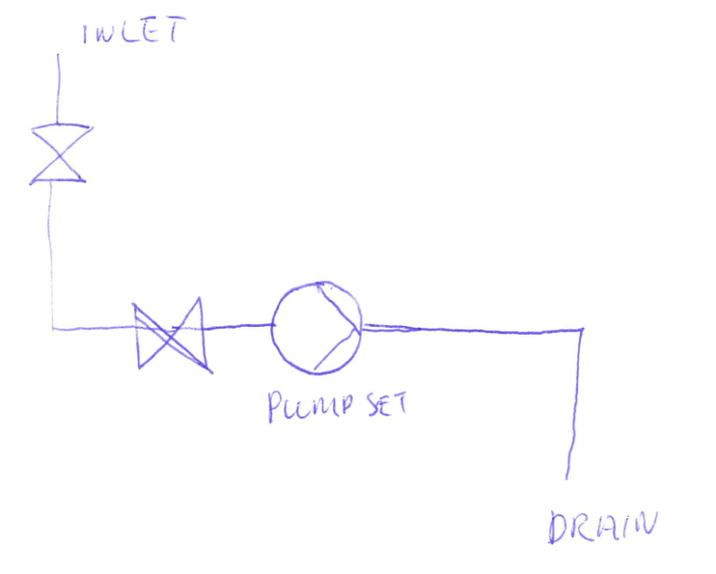
There is no re-circulation line at present, it would just go to drain.
The total circuit for the drain line so far is approx 10 meters which is around 10 litres volume.
Just adding a re-circulation line without tank would be again, 10 meters, around 10 litres volume, total of 20 litres.

The inlet pressure is around 6-7 bar, there is no main tank to come back to, it all comes in from the supply line.
Screenshot_2022-03-10_132832_t0kuvg.png


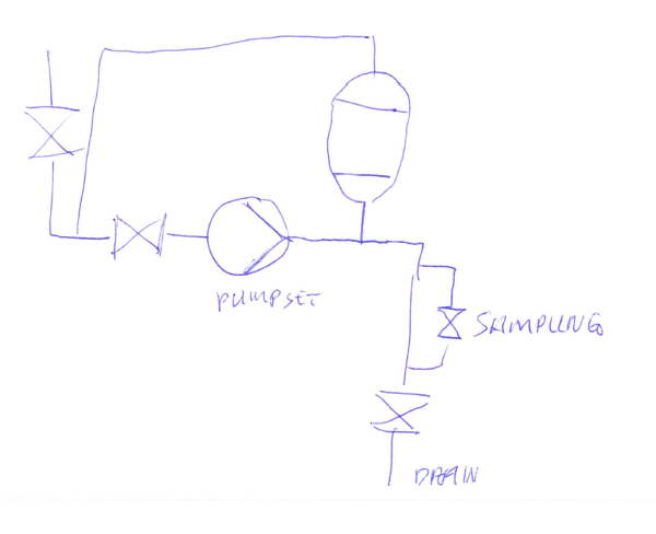
If I add the recirculation line, tank and sampling it would look like this:
Screenshot_2022-03-10_132904_uftfim.png


If it's all the shaft power I have to account for then I need a tank around 1 tonne in size to limit the temperature rise to less than 10degC.
By c=Q/m*delta_T
 
Basic question I forgot to ask is what do you mean by "test"??

1) Do you mean "full power" test where there is a pressure drop between the discharge and the inlet of 100 - 7 bar at full flow?
OR
2) A flow at full flow but with virtually no pressure drop?

As PD pumps do both then you need to determine what it is you're trying to do. Option 2 would use a lot less power and hence work done on the fluid so temperature rise would be much reduced.

You don't show the pressure control valve anywhere so it is looking like option 2 at the moment...

If in recirc mode that valve upstream of the recirc tie in closed then your inlet pressure will rise rapidly as temperature increases so if your test is option 1, then you would need to control the inlet pressure to 6-7 bar which requires a control valve or pressure relief valve set at say 10 bar?

what's the strange looking oval shaped thing on the recirc line? = A pressure vessel??

Remember - More details = better answers
Also: If you get a response it's polite to respond to it.
 
There are two types of test, once a year a full system test with the water coming from the inlet, and would bypass the re-circulation system and go straight to drain. This would be equivalent of test Option 1. There is no back pressure that would usually be present if the system was operating in it's intended function, but that can't be tested directly.

Once a week, there would be a pump test. This would be equivalent to option 2, but the pressure needs to dissipate before being put back into the inlet. Could be an option to prime the system with fluid from the inlet, and then close off the inlet and circulate that load of water.

The actual P&ID is more complicated, I tried to simplify. The weird oval is meant to be a tank, I would add a tank to add fluid mass and heat dissipating area to the system, otherwise there is too little fluid mass. The problem here is if this is filled with water, then there will be no pressure relief.

For the re-circulation, the pressure would have to dissipated, using a larger diameter pipe as 1503-44 suggested, potentially the tank if it starts empty, but even that provides a little over a minute of test time per tonne of capacity. Any other options?

 
If I understand this correctly your pumps, when used in an emergency, are required to pump 40m3/hr at 100 bar discharge pressure to some system somewhere.

For test purposes, this line from the pump can be connected to a drain instead of the system? But you don't throttle the discharge to create 100 bar discharge pressure?? Then to me it's not a proper test as you're not working the system to its full extent. You should have a control valve / pressure regulating valve that opens at 100 bar to the drain (only for test purposes)

To recirculate to prevent wastage you could in fact just pump round and round a circuit to show the pumps "work" - i.e. my option 2 if you can prime your system. To me that's not as good as testing the system with a high differential pressure, but it might be enough to do that and then test it in anger by going to the drain once a year?

I'm getting a little lost as to how this system functions, but hope I've explained this better now.

Remember - More details = better answers
Also: If you get a response it's polite to respond to it.
 
You don't need that much water.
Est efficiency at 70%
70% makes head. Only 30% makes heat.

At 750 l/s 100 bars, running 4minutes needs only about 1000 lbs of water (0.45 m3) circulating to keep it from rising past 10C°

29ft, say 10m of 6" DN150. OK, make it 8"

A black swan to a turkey is a white swan to the butcher ... and to Boeing.
 
Yes, you've got it.

There is no throttle valve at present, i agree this could be added to improve the validity of the full system test, thanks for this suggestion.

The problem comes from the small volume of the re-circulation system, the closed loop, option 2, pumping round and round. How to reject the heat and pressure from this system, most of 125kW for 5 mins. That will quite happily boil 100 litres of water in 5 minutes.

Do I add a 1000L tank, long finned radiator pipes, a heat exchanger?
 
So is it all of the shaft power that needs to be accounted for, 125kW?
OR
only the inefficiency that makes heat? Say 30% of 125k = 37.5kW?
If so, where does this pressure go, can I just dissipate it somehow? Like a outlet spray nozzle into a tank. If this was in steady state, wouldn't the tank just fill up?
 
If you have a large pressure drop in your recirculation system then yes, you're looking at 125kW.

Mr 44 - If the fluid was forward flow then the temp rise is limited to the efficiency figure - these are PD pumps remember. But once you drop 93 bar across a regulating valve then the energy you've put into the fluid in terms of head needs to go somewhere surely?

however if all you are doing is going round in a circle with very little pressure difference across the pump, the energy in the fluid from the pump is much lower and hence the temperature rise much lower. Just because your motor can use supply 25kW doesn't mean it will do that unless the power is required.

House888 - where is your normal pressure relief / recirculation for these pumps? PD pumps always need to allow for blocked discharge??

Remember - More details = better answers
Also: If you get a response it's polite to respond to it.
 
Where the water goes does not change where its been. Do the energy balance. Only (1-eff) x brake power expended is available for heating. The rest produced "useful work", In the energy sense, it is just a basic machine. No matter what kind of pump, or windmill it might be.

Take (1-the efficiency given for each flow rate) x brake power expended at that flow rate and convert to J/s and that's your heat rate at that flow rate. A PD pump will generate the head needed to get whatever its flow rate is out the discharge, at least until it runs out of power, or blows up. To calculate discharge pressure or head, you just need the system curve.

It's basically isothermal flow across the valve.

Yes, I figured the water mass required at full flow and pressure. If he can do the test at lesser values, heat generated will probably drop, which will also only require proportionally less water mass. Depends on what the efficiency is at lower flow rates. But you said if not done at full power, its not a proper test. I dont know. Sometimes on weekly tests you really just need to see if the motor turns on. No information. Anyway for a full test, 10m of DN150 will run for 4min at 100B with max 10C° heating, if the eff is 70%.

A black swan to a turkey is a white swan to the butcher ... and to Boeing.
 
I am unwilling to spend the time to figure out all the details of how your system works, but here are some things for consideration. In recirculation the pump efficiency is zero, not 70%. Your options for draining are not limited to yes or no. You can drain a small percentage of flow so that cooling water can be added to the suction flow of the pump.
 
If the pump is recirculating flow, its making some head and consuming power. Impossible to have flow at 0% efficiency, maybe 1%, and unlikely to have been done at 100%. That leaves it in the range of > 0 and < 100. Not 0. What's the pump "curve" say? Even piston pumps have a "curve", actually more like a straight, nearly vertical line.

A black swan to a turkey is a white swan to the butcher ... and to Boeing.
 
First law of thermo. Tell me which 1% you are talking about. Then I can tell you where its going. There is 100% of the shaft power available. Is your 1% generating head, or heat? If you say head, then it's generating head and the remainder is generating heat. If you say heat, than 1% is generating heat and the remainder is generating head. You can't get one without the other, except when motor is running, 0 head generated, but fluid is not moving internally or externally(a bit difficult, but I'll allow that possibility for discussion purposes). After pipe, fitting and valve friction losses, 100% of power has been expended and all of has been converted into heating the fluid, pump and pipe walls, then the surrounding environment and then the universe in the end. If the motor is running and there is no flow internally or externally to the pump, then "pump efficiency" is indeed 0, no head generated and all power being consumed within the system (control volume includes pump, piping, fluid and shaft) is being converted to heat. That makes it 100% efficient at generating heat and 0% efficient at generating head... theoretically.

A black swan to a turkey is a white swan to the butcher ... and to Boeing.
 
1503-44 100% of the power going into a recirculation loop becomes heat, as I stated before. You are the one who brought-up a figure of 1%, so please explain to us where this energy is constantly going if not into heat.
 
I said (pump) efficiency must be >0 and <100. Pick any number you want.

Of the total power (rate of energy expended) used in a pump system, some is converted into pressure-head, velocity head and sensible heat. We know how much of each results, as we have a pitot tube, a pressure gage and a thermometer. Total Pump Efficiency is defined in terms of power input vs hydraulic power output, that output excludes any power converted to sensible heat. It includes only potential energy expended and kinetic energy expended, pressure head and velocity head. Yet power input includes all energy that will be converted to any and all forms of output, Thus it includes any energy that is converted to sensible heat. Pump efficiency describes the part converted into "useful work". The remainder is converted to sensible heat. What is the remainder? The remainder is = Power Input at the shaft * (1- Total Pump efficiency) = sensible heat.

Potential energy goes to the Pressure gage. Increasing the fluid pressure.
Kinetic energy goes to the Pitot tube. Increasing the fluid velocity.
Sensible heat goes to the Thermometer. Heating the pump and fluid (via both mechanical and fluid friction). We assume that the energy consumed by mechanical friction heats the mechanical parts and that consumed by viscos shear forces heats the fluid, although it is not so well defined and some cross heating occurs. Obviously a hot pump wall can heat some fluid adjacent to the inside wall and v/v. Some heat leaves the system through the pump wall. The balance raises the pump wall temperature. The portion of heat remaining in the fluid increases the fluid temperature and hot fluid is carried to the piping. Some of the fluid heat increases the pipe wall temperature, of which some of that is given off to surroundings. The remainder of that heat stays in the fluid Increasing the temperature of any downstream fluid that it mixes with. The pressure is "lost" to frictional heating of the fluid and the pipe wall, both of which increase their temperatures. Some heat is again lost by the pipe wall to its surroundings. The average temperature of all fluid is increased as it mixes with cooler downstream volumes. If that fluid is in the recirculation piping, it will begin heating more so when it reaches the pump. If it leaves the system, we are no longer interested in what happens to that.

If you don't like 1% efficiency, fine, pick 10, 15, 20, pick 30%, or 70%, whatever seems reasonable to you, or better yet look at the pump curve and pick the efficiency that corresponds to your flow rate, then run the numbers. You will know where it all goes and you won't have to ask anybody ever again. Which is good, 'cause its way past my bedtime.

A black swan to a turkey is a white swan to the butcher ... and to Boeing.
 
Would agree that all power expended at the pumps, in a total recirc loop with no net feed, will appear as heat in this closed loop, assuming heat dissipated to air from pump casing and pipework is next to nothing. So for each pump, you've got 25kW to absorb within closed system + dissipate to air + dump to drain over 4min = 6000kJ.

Check with pump vendor if 45degC is really the upper limit of operation for these pumps, it should be higher. There shouldnt be any NPSH issues, since suction pressure is 6-7barg. The actual upper limit may be related to rod packing, since these are PD pumps.

In reality, you cant have a fully closed inlet. If you do, in a fully closed system with no gas volume, suction pressure will rise to infinity as closed system temp rises, since expansion of heated liquid has nowhere to go. You should have the feed valve slightly open to maintain suction press at 6-7barg, and drain off this small net feed at pump discharge on pressure control. This net forward flow to drain will absorb a lot of the heat generated by the pump also.

If I take credit only for heat dumped to drain, you have a steady state operation; assuming you are permitted to rise 20degC, then you need to dump 18 litres/min per pump. Which is obtained as follows:
Heat generated per minute = 6000/4 = 1500kJ/min
Assume temp rise (from 30degC at fresh feed at suction rising up 50degC) = 20degC
Water Cp = 4.18kJ/kg/degC
Water to be dumped on net forward flow to drain = 1500/20/4.18 = 18kg/min = 18 litres/min.
So for 5 pumps, < 100 litres/ min. So for 4min test time, < 400litres dumped total.

You may not need a backpressure PCV on the drain line to control discharge pressure. If suction pressure is constant, even a plain gate valve on the drain line can be manually throttled to give you 100barg. Then throttle the recycle valve to give you the desired temp rise in the circuit. Or you can do the converse : throttle the recycle valve to give you 100barg, and throttle the drain valve to get you to the desired temp rise.

 
If not operating at full power, 125kW is not available to the pump. I suggest you substitute a power input variable for your 125kW number to allow for operation at slower speeds.

"In reality, you cant have a fully closed inlet. If you do, in a fully closed system with no gas volume, suction pressure will rise to infinity as closed system temp rises, since expansion of heated liquid has nowhere to go. You should have the feed valve slightly open to maintain suction press at 6-7barg, and drain off this small net feed at pump discharge on pressure control. This net forward flow to drain will absorb a lot of the heat generated by the pump also."

Disagree. A fully closed inlet (to the pump) will do just the opposite. Suction Pressure will either be reduced until cavitation begins, the liquid's vapour pressure is reached, at which time water vapour fills the inlet. If the water vapour enters the cylinder, the piston compresses it thereby violently collapsing the vapour back to liquid. The cylinder pressure is reduced back to the vapour pressure at which compression cycle began. Pressures, now being equal between suction entry point and inlet to the cylinder, no additional fluid can enter the cylinder. Efficiency drops to 0, Friction heats the pump and vapor. Temperature rises (probably not infinitely), but now you probably wrecked the pump anyway with cavitation and implosive vapour collapse.

Yes, the inlet should be open allowing the recirculated water, or new makeup water to enter pump
suction with sufficient NPSH. But no need to drain any flow if you have recirculation back around to suction. Simply end it back to suction a little warmer.

"You may not need a backpressure PCV on the drain line to control discharge pressure. If suction pressure is constant, even a plain gate valve on the drain line can be manually throttled to give you 100barg. Then throttle the recycle valve to give you the desired temp rise in the circuit. Or you can do the converse : throttle the recycle valve to give you 100barg, and throttle the drain valve to get you to the desired temp rise."

Again, a no. If you assume operating at full power, as you have, you will certainly need a means of controlling the 100bar discharge to the drain. If an open drain, keep your feet away from that 100 bars. Assuming you haven't blown out the catchment and drain pipe already, or the gate valve. If you try to reduce the 100 bar discharge (to atmospheric pressure) to keep from cutting the catchment basin in two, that gate won't last long. Cut in two.

Another no. If you have recirculation back to suction, and the test is at full power, you should put in a PCV to burn up any pressure in excess of the required NPSHr. At 100 bars, you may actually need two control valves, so you can take 50b pressure drop at each one, to try to avoid a 100b valve cavitation flashing, wear and destroying the valves. You should avoid full power testing if possible.

Above experience gained from operating 400m3/hr, 225 barg, product pipeline pumps with recirculation back to suction. Recirculation back to suction was required, not to drain, because you don't dump gasoline, diesel and jet fuel into drains. Recirculation was required, because the 3000 kW diesel driven pumps required 15min at idle and runup for reaching operating temperature and the 17.5Bar discharge pressure needed to force the discharge check(NRV) open for flow into the pipeline. 1750 bar recirculation required 2 PCV's with anti noise/cavitation trims. Still they did not last much past 6mos before overhauls. The 3000 kW pumps would reach 150°C when operated on recycle for 20 minutes. Yes we had a recirculation tank. I'm pretty sure I know where the heat goes. Up to you House888. Take it, or leave it.

If you can test at lower flow and pressure, do it.

A black swan to a turkey is a white swan to the butcher ... and to Boeing.
 
Status
Not open for further replies.

Part and Inventory Search

Sponsor