Eng-Tips is the largest engineering community on the Internet

Intelligent Work Forums for Engineering Professionals

Reaction force from part rotation stopping 1

Status
Not open for further replies.

kyleShropshire

Mechanical
May 22, 2022
22
0
0
US
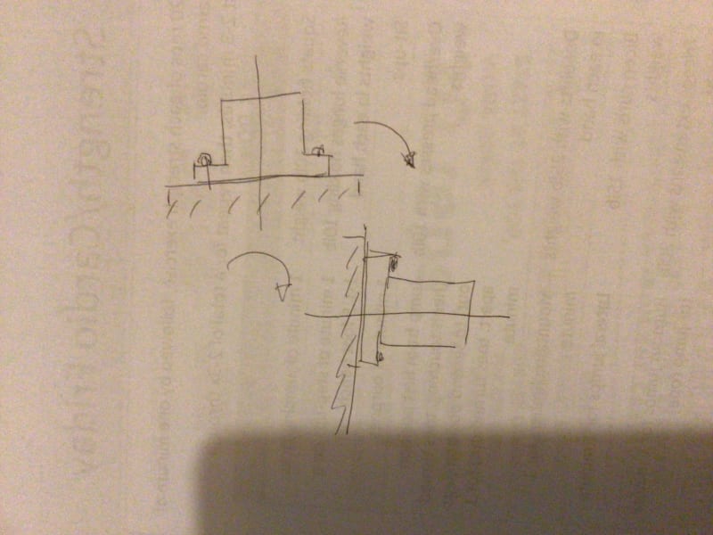
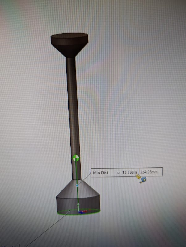
I have a cylinder rotating about its base.
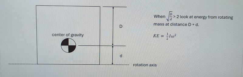
When I decelerate to a stop is there a point where the ratio between the mass at the outer fibers and the center of gravity make a difference in calculating the reaction force?

The cylinder base is bolted down with four bolts and I am calculating the design factor on the bolted joint.

I was recently told this matters and want a second opinion.

PXL_20240417_155106151_qrl6dg.jpg
 
Replies continue below

Recommended for you

Hi KyleShropshire

Why is the centre of gravity not on the centreline of rotation?

When the cylinder decelerates and the centre of gravity is offset then I can see that the bolt reaction to shear will vary in each bolt but that assumes that the bolts are positioned equally around the axis of rotation.

If you can show us a sketch of how the bolts are positioned relative to the centre of gravity and the axis of rotation then we may be able to help further.

“Do not worry about your problems with mathematics, I assure you mine are far greater.” Albert Einstein
 
The cylinder has a flange on the base that is bolted to a tilting table. Imagine the cylinder axis being perpendicular to the floor and then tilted by the base until the axis is parallel with the ground.

Assume the bolts are equally spaced with one at the 12 oclock position.

I am looking for the difference (if any) from calculating the reaction force when tilting a cylinder that has a D/d=1 vs D/d=4.
 
Just wondering, if an object is rotating about its own axis and that axis is also moving (rotationally accelerating / decelerating about its attachment point), would you need to i) consider gyroscopic effects and / or ii) inertia forces about the two axes of rotation simultaneously? It’s been a long time since I left uni and done such calc’s!!
 
I haven’t researched the case, but I think you’d need to first derive your equations for forces and moments / torques with respect to time. This will enable you to determine the highest loading condition, when taking into account the changing accelerations. You may have a number of loading cases or an enveloping case. Once you’ve got the cases, you could use a 2D bolt group analysis to calculate the bolt reactions. Hope this gives some ideas and proves helpful!
 
Thanks for the help so far. I have already done the bolted joint calcs and have that worked out.
The question is about identical moment of inertia values but mass distribution changing.

Does the reaction force change based on D/d ratio from center of mass as shown in my first message?
Or does this ratio indicate when additional calcs are required to handle non-uniform mass distribution.

Both images below have identical Izz of 20.6 kg*m^2 and are both 1 m in height. The D/d ratio changes from D/d=1 on the nominal cylinder to D/d=2 on the odd looking part.
PXL_20240418_140907175_atcdf5.jpg


PXL_20240418_140933528_bgaxvh.jpg
 
Hi KlyeShropshire

I’m sorry but I am not really understanding the D to d ratios on the diagrams it doesn’t say what D or little d is and nor does it show any bolts, can you give us a clear picture of exactly what the components look like please.
I assume the large D refers to the large diameter and the small d the small long diameter but other than that the rest is meaningless to me sorry.

“Do not worry about your problems with mathematics, I assure you mine are far greater.” Albert Einstein
 
D is distance from top of part to center of gravity.
d is distance from bottom of part to center of gravity.

The bolts themselves are not relevant to the question and can be ignored, I only mentioned them as a description of how the real part is attached to the tilting table.

The force required to hold the cylinder in place during decel is what I'm looking into.

I want to know why I was told the odd shaped part would need a larger force to keep it in place even though the mass moments of inertia are identical. (I tried to get answers from the person who told me this but they did not really have an explanation other than to just expect larger forces when D/d increases above 2.)
 
The force depends on the acceleration profile. It can be anywhere from zero to very high.

Energy is 1/2 I w^2 + mgh. If h, the distance the CG travels, changes the energy will also change.

 
Yes, the CG height is lower on the strange shaped part. Which made me believe a smaller force is required to hold it in place since the inertia and mass are the same as the cylinder.

But I was told the reaction force would actually increase, even though the CG is closer to the mounting end of the part. This doesn't make sense to me at first glance.

However, the engineer that told me this has many years of design and lab/field testing experience. I think it would be a mistake for me to just ignore the statement because it doesn't align with the basic energy equation. I believe I am missing something (probably obvious) that would explain this.

 
Correct, as stated above I already asked. They couldn't explain it. Just when the ratio D/d was over 2 to "double the force".

I have one idea that it could be due to the part geometry. The concentration of mass at the far end could need to be treated as a separate part with it's own cg and not base everything on the total part cg. Perhaps the increase in rotational speed at the far end gives that mass an increased effect.

Or perhaps the part flexes in the center as it decelerates to a stop and that increases the force.
 
What equations are you using to determine the force at the base? Would it not be the sum of the dynamic force due to acceleration/deceleration plus force due to static weight of cylider, and resulting/force moment reaction at the base for both of these forces?

Dynamic Force of acceleration/decleration:

F = M*R*A

F = Force in pounds
M = Total mass in slugs Weight/g
R = Radius of motion of C.G. in feet
A = Angular acceleration dW/dt = R d[sup]2[/sup]Theta/dt[sup]2[/sup] in radians per sec-sec

So this produces a shear force and moment about the base. The shear force is same but the moment will increase with R. If R doubles then moment will double and so will opposing forces/moments in bolts.

Same for gravity reaction force - as R increases, shear force is same but moment reaction forces increase.

So if D/d doubles the moment reaction will half.
 
Status
Not open for further replies.
Back
Top