Continue to Site

Eng-Tips is the largest engineering community on the Internet

Intelligent Work Forums for Engineering Professionals

  • Congratulations KootK on being selected by the Eng-Tips community for having the most helpful posts in the forums last week. Way to Go!

Reaction force on shear coupling. 1

Status
Not open for further replies.

CADCAMTech

Mechanical
Nov 10, 2015
33
I would like to compare my hand calculations to a FEA simulation. Here is the original question I posted regarding calculating the force generated by the coupling to shear some set screws:


In the image below, I have applied an internal pressure of 3000 psi to the surfaces with green arrows. Then I fixed the bottom surface in all directions. The bottom surface is on the right hand side of the image.
I am using Autodesk Nastran In-Cad with the following settings
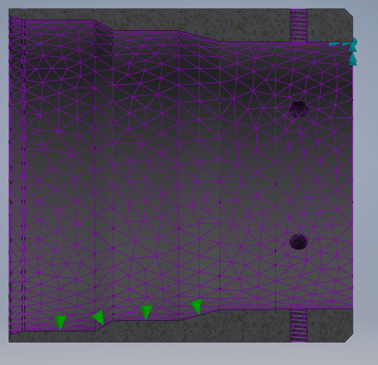
solid elements
with the analysis set to linear static
material is steel​
Capture_gdhxda.png


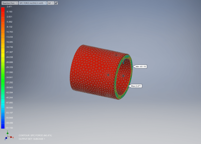
My hand calculations tell me that there should be 7950 lbf reaction force in the x direction, but the simulation is only showing 61 lbf so clearly I have set up something wrong. It has been quite awhile since I took a course on FEA so that is probably part of my issue.

I am open to any suggestions, if you need more information feel free to ask. Thanks.
 
Replies continue below

Recommended for you

"I have applied an internal pressure of 3000 psi to the surfaces with green arrows. Then I fixed the bottom surface in all directions." ... so then the fixed support is reacting the load ? If there is a ground on the other side of the flange, then the two screws will see no load.

another day in paradise, or is paradise one day closer ?
 
rb1957,
I Fixed that face rather than the screw holes just for simplicity. I am not interested right now in what is going on at the screw holes, i'm just interested in the total reaction force on the coupling itself.
 
is "x" in the direction you think it is ?

another day in paradise, or is paradise one day closer ?
 
Yep I think so, the coordinate system in the lower left of the image below shows x in the direction I would expect it.
Capture2_y4n7j1.png
 
so to align the 1st pic with the 2nd, x in the 1st is horizontal ?

another day in paradise, or is paradise one day closer ?
 
rb1957,

Correct, the two pictures are from the same screen, one is from the setup view and the second picture is after the simulation is ran.
 
then if you're apply pressure (like the green arrows) then why would you look for a large component in that (horizontal) direction ?

another day in paradise, or is paradise one day closer ?
 
rb1957,

When in use, the pressure applied to those ID faces cause the fitting to slide horizontally in the picture. There are shear screws in the holes you can see in the pictures that resist this horizontal motion until they break. At this point the sleeve slides all the way down and relieves the internal pressure. Does that help you visualize what is doing on?
 
I was noting that the projected area normal to X seems quite small ?

another day in paradise, or is paradise one day closer ?
 
The projected area normal to the y-z plane is 2.65 in^2.
 
ok, that's in line with your calc. Where is the model showing 61 lbs ? What other constraints are reacting this applied load ?

Try a test case, applying 1000 lbs Fx at a point to see where it gets reacted ?

another day in paradise, or is paradise one day closer ?
 
I think I may have found the issue. After I completed the simulation there was a drop down menu to view something called Reaction Forces, which had the options to view:
SPC Force Total
SPC Force Along X
SPC Force Along Y
SPC Force Along Z​

I did not understand that SPC Force indicates "Single Point Constraint" force which I am still not totally sure what that means, but I found a help page (Link) that showed me how to do a summation of all of the SPC Forces.

Once I enabled that option it gave me a resultant force of -8016 lbf in the x-direction which is close to my calculated hand value of -7952 lbf in the x-direction.

rb1957 thanks for your suggestion regarding using a simpler test case. I tried that and I ended up with the same wrong result I was getting before, but in doing that I knew for sure that something was wrong and it led me down the right path
 
thx for the LPS. always happy to help someone out of the woods. I'd recommend some training or tutorials.

another day in paradise, or is paradise one day closer ?
 
Yeah I am going through some autodesk training tutorials right now. I was trying to work off my memory and it obviously was not good enough. Hopefully I can start to use this program more to make some of the information stick.
 
A spc is a boundary condition on a node. It could be that a node on one beam end has been fixed in all 6 degrees of freedom (a cantilever). So it is a node restraint. Thus a spc force is the resulting reaction force on such a restraint when a force is applied. In general the sum of all the spc reaction forces should be equal to the total applied load (for a well defined model at least, it not something might not be correct).
 
Status
Not open for further replies.

Part and Inventory Search

Sponsor