MIStructE_IRE
Structural
- Sep 23, 2018
- 816
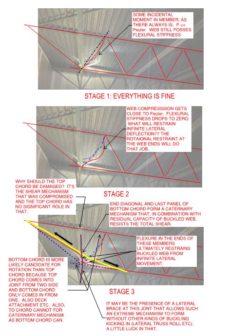
I was called out to look at this truss which has failed. Its a Steel warren roof truss. The layout is shown below - but I’ve crossed out the vertical which doesn’t exist - which I think should have existed!
It looks to me as though the second last diagonal, the compression member buckled due to excessive compressive force, and as it buckled it pulled the last diagonal, which should be in tension, causing it to buckle also.
Any thoughts on the mechanism? There are hundreds of these trusses throughout the building and this one has failed.
Disclaimer - not my design!! I just got asked to review this failure!
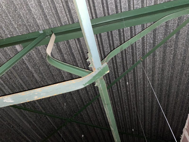