Continue to Site

Eng-Tips is the largest engineering community on the Internet

Intelligent Work Forums for Engineering Professionals

  • Congratulations KootK on being selected by the Eng-Tips community for having the most helpful posts in the forums last week. Way to Go!

Reallly long panel feeder -- how to connect to panel and feeder breaker?

Status
Not open for further replies.

DRWeig

Electrical
Apr 8, 2002
3,004
Hi Fellows,

I'm working a project involving great distances from a main switchboard or power panel to some 250A 480/3 panels. The champion is an 850-foot run. In order to keep voltage drop to less than 3 percent, I calculated the need for 4 sets of 350 MCM per phase at an 80 percent load on the panel (200A) for this longest run.

My question is, I haven't found a 250A panel that can accept 4 x 350 MCM per phase at the main lugs, nor a switchboard breaker that can do so either. Do we need to spot a wiring box at each end to reduce the feeder size to "normal" (1 x 250 MCM) at each end?

Sorry for the elementary question -- I've just never run into these distances before. I've always been able to space my mains as needed to reduce feeder distances, but not in this cavernous building...

Thanks for your help!

Best to you,

Goober Dave

Haven't see the forum policies? Do so now: Forum Policies
 
Replies continue below

Recommended for you

Yep, take a short run of normal sized conductor to a suitablely size j-box and install some form of splice block for the transition to the larger conductor.
 
How about "Reducer pins"?
Link

Bill
--------------------
"Why not the best?"
Jimmy Carter
 
What Waross said, reducers. Split bolts and lots of tape would be another solution.
 
Thanks folks,

That's what I was thinking too...

Best to you,

Goober Dave

Haven't see the forum policies? Do so now: Forum Policies
 
For diesel generating sets we use a 'link box' to connect the generator to the network. This is because the sets usually sit on anti vibration mounts, and you cannot use armoured cable directly to the generator terminal box, because it is too stiff. So you have a short run of flexible cable, then transfer to armoured at the link box.

What you are looking for is essentially a link box. But between two sets of armoured cable. Try asking a generating set packager or a panel maker, they will have them, so you don't have to re-invent the wheel.

Sorry for the long explanation.
 
Group each set of four conductors onto a pair of commercially-available stud terminals with a link bar across them, and take something more manageable out to the load and source. Something like Weidmuller's WFF series would be a good choice.
 
Thanks Hoxton and ScottyUK! Great ideas. I'm working with a generator on this job, too -- so I'll ask the Cat rep about the link boxes. I'll show the boss the stud terminals, too. I can size a box for them near each end of the feeder.

Best to you,

Goober Dave

Haven't see the forum policies? Do so now: Forum Policies
 
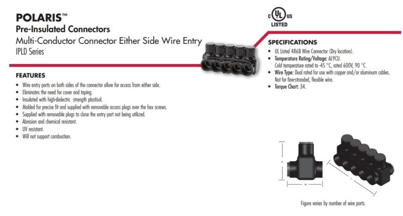
I'm a big fan of Polaris insulated connectors. They aren't the cheapest option, but they make for a clean install and you're already spending a lot on your conductors.

-JFPE

Polaris_IPLD_series_abs4il.jpg
 
Thanks jfpe,

I'll have a few options now for my client. Eng-tips rules!

Best to you,

Goober Dave

Haven't see the forum policies? Do so now: Forum Policies
 
I seem to recall hearing of someone who had a really long run like that to contend with, and the question being posed whether the total cost of a step-up and step-down autotransformer at each end combined with lighter cables between them [provided the operating voltage did not exceed 750V] would be cheaper than the cost of just the heavier cable plus the splitters & j-boxes.

CR

"As iron sharpens iron, so one person sharpens another." [Proverbs 27:17, NIV]
 
Thanks, crshears. In fact, I was asked to analyze that this evening as I left work. Buck/boost could be the way to go. I really like those Polaris connectors, too, though... It'll all boil down to $$.

Best to you,

Goober Dave

Haven't see the forum policies? Do so now: Forum Policies
 
I would call this step-up, step-down.
In my experience buck, boost most often implies auto-transformers.
In your case, you will probably be looking at about 4160 Volts.
An auto transformer is NOT recommended.
An open circuit on the 480 Volt winding on the receiving end will put 4160 Volts where you are expecting 480 Volts.
Also, the advantage of an auto-transformer over a two winding transformer is slight with a step up ratio of 4160:480, or 8.66:1 Auto-transformer boost is most economical with small ratios like 1:4 (eg: 120V + 480V = 600V)
The higher the step up ratio the less size advantage to an auto-transformer and the more danger in the event of an open circuit secondary winding.
I love auto-transformer applications, but there is a limit.

Bill
--------------------
"Why not the best?"
Jimmy Carter
 
Thanks Bill, I had not thought of that. I'll draw it out for them...

Best to you,

Goober Dave

Haven't see the forum policies? Do so now: Forum Policies
 
Status
Not open for further replies.

Part and Inventory Search

Sponsor