Continue to Site

Eng-Tips is the largest engineering community on the Internet

Intelligent Work Forums for Engineering Professionals

  • Congratulations GregLocock on being selected by the Eng-Tips community for having the most helpful posts in the forums last week. Way to Go!

Recommended Pump Suction and Discharge Side Velocities

Status
Not open for further replies.

Pavan Kumar

Chemical
Aug 27, 2019
347
Hi All,

I wanted to get hold of a standard reference which mentions the recommended velocities on pump suction and discharge sides for a centrifugal pump. I understand the on the pump suction side NPSHA governs the velocity but a general guideline and reference would be very helpful. One of the online reference, link copied below, mentions the recommended pump suction and discharge velocities as 3-6 ft/sec and 9-12 ft/sec respectively. Norsok standard P-001 Rev 3 mentions the maximum velocities which look more erosional velocities. I am looking for more like a company standard or some good engineering practice document that mentions this.


Thanks and Regards,
Pavan Kumar
 
Replies continue below

Recommended for you

Hi TiCl4,

Thanks for your detailed answers. I will read through the sections in Perry.

There could be an increase in particle size due to process upset, definitely possible. The 3" suction pipe seems suspect for plugging during a process upset. I will have to do the calculations like you did to confirm this. I cannot reduce the line size to 2" due to NPSH considerations. So I think I have to live with 3" pipe. At least I know it is suspect. We are going to have air/ steam blow out points on pump suction and discharge. We will use these to clear the lines if they get plugged.

Thanks and Regards,
Pavan Kumar
 
Hi Littleinch,

We have not purchased the pump yet. I am still finalizing the pump sizing. I however received quotes from vendors. I plotted my system curve against the pump curve and found them to intersect at 85 gpm instead of intended 75 gpm flow. Thats why I said I will need to throttle my discharge valve. I asked for the BEP points shown on the efficiency curves that the vendor was asked to send to see how far from BEP I will operate my pump. The motor is sized for End of Curve power requirement which is 4.07 HP.

Please see my Pump sizing Calculation attached. I have a question here. For the suction and discharge side frictional pressure drop calculations I am using the Equivalent Length method with equivalent lengths taken from Crane TP-410 A-26 to A-29. I have used the same friction factor that I calculated for the pipe for both the pipe and fittings. I have read posts by Mr. Harvey Wilson( Katmar) and Mr. Leckner on CHEE resources forum that we need to use the friction factor (fT) in complete turbulence listed on the first table on A-26 on Crane TP for the fittings. So the pressure drop equation would read

DP/RHO = [f(L/D)+ N x fT(Leq/D)] x (V2)/(2 gc)

where DP is the pressure rise across the pump,

RHO is the fluid density

f is pipe friction factor calculated using Churchill equation

L is straight pipe length

D is the pipe inside diameter.

Leq/D is the equivalent length of fittings from Crane TP-410 A-26 to A-29

N is the number of fittings of each kind.


The head developed by the pump drops to 55.6 feet from 61.4 feet when I use fT instead of f for the fittings.

I want to know how do you guys size a size pump. I want to make sure I am doing calculations correctly.
Your review and comments will help me greatly.

Thanks and Regards,
Pavan Kumar


Would be good if you could go for the 2inch suction line, but NPSHa margin to NPSHr is zero from what you say. Can you increase source vessel low level alarm liquid level, or increase vessel height to get a few feet margin on NPSH to enable a 2inch suction?
There should not be any low point pockets in the suction piping in any case. Check that you have a vortex breaker on the source vessel liquid exit, and that there is sufficient gap between this low level alarm and top of vortex breaker to enable adequate degassing of the liquid.

NPSHr estimates from pump vendors are based on cold water as test fluid. Apply correction factors found in Perry to get the reduced corrected NPSHr for hot water - see Fig 10-25 in 7th ed of Perry for correction charts, which is abstracted from the Hydraulic Institute Standards. This may help to enable sufficient margin and a 2inch suction I think.
 
What pump speed are you considering?

It is a capital mistake to theorise before one has data. Insensibly one begins to twist facts to suit theories, instead of theories to suit facts. (Sherlock Holmes - A Scandal in Bohemia.)
 
Hi Artisi,

The pump speed the vendor suggested me to consider is 1750 RPM to reduce the abrasion due to solid particles. Earlier consideration was for 3600 RPM motor.

Thanks and Regards,
Pavan Kumar
 
Hi georgeverghese,

I possible can increase the low level alarm. With low level alarm at 5 feet NPSHA is 7.77 ft. The question is how much above NPSHR should NPSHA should be. Normal operating liquid level is 13.58 feet.


Thanks and Regards,
Pavan Kumar
 
Why is NPSHa 7.7ft?

It is a capital mistake to theorise before one has data. Insensibly one begins to twist facts to suit theories, instead of theories to suit facts. (Sherlock Holmes - A Scandal in Bohemia.)
 
You asked how to size a pump, it's about 5 minutes work for a pump application engineering.

What are you pumping
Flowrate (minimum /maximum)
Pipe length - inlet side, delivery side
Static inlet head (+ or-)
Static delivery head
Velocity in suction pipework required at design flowrate
Select pipe size
Calculate headloss (suction side)
Same for deliver pipework

Add suction headloss and delivery headloss plus static head.

This gives you the total head at design flowrate.
What is NPSHa at design flow
Select pump capable of Q/H with sufficient NPSH margin.

This is a basic selection, pump materials, speed etc is another step based of customer preference / specification / best practice.

Job done - select next pump for next application.

Added: correct for altitude and product temperature.


It is a capital mistake to theorise before one has data. Insensibly one begins to twist facts to suit theories, instead of theories to suit facts. (Sherlock Holmes - A Scandal in Bohemia.)
 
Pavan,

I believe you ate calculating NPSHa incorrectly. 78 gpm in a 2” pipe is only something like 7 psi/100 ft line losses. Unless you have a very, very long suction pipe run, your pump is elevated, or your tank is under vacuum, there is no way you only have 7.7 ft actual head available. Are you adding atmospheric pressure into your NPSHa calculation?
 
Try to get a margin of approx 3ft between NPSHa and NPSHr.
At 65degC pumping temp for hot water, NPSHr reduction is minimal from fig 10-25 in Perry, so you have to work with 6ft NPSHr.
Another cautionary point to account for at 2inch suction with this high 7fps stream velocity is that all degassing must now occur in the source vessel. Run the calcs for 300micron gas bubble terminal rising velocity in the source vessel at LAL / max throughput and check that bubble upward velocity is higher than downward liquid velocity. The pump nozzle arrangement must also enable continuous degassing of the casing to keep the casing fully primed - the discharge nozzle must be at the top of the casing.
 
Hi TiCl4,

The calculation done in my excel spreadsheet is shown below. Also please find my pump calculation spreadsheet attached. Please let me know if something is wrong.

Input Data:

Fluid = Waste Water
Temperature, T = 85 Deg C
Density, RHO = 66.646 lb/ft3
Viscosity, Mu = 10 cP = 0.006719 lb/ft-sec
Vapor Pressure, Pvap = 8.38 psi

Desired Pumping Rate = 75 US gpm = 0.1671 ft3/sec

Minimum Liquid Level in Tank = 5 feet From Grade
Pump Suction Flange Elevation = 1 feet from Grade

Suction Piping:

Length, L = 30 ft ( Considered max length as the pump location is not yet fixed, actual length may be just 15 feet)
Line Size = 2 Sch 10
Inside Diameter, D = 2.157" = 0.1798 ft
Pipe Roughness,e = 0.0018"

Fittings:
1. Pipe Entrance = 1
2. 90 Deg LR Elbow = 6
3. 45 LR Elbow = 2
4. Gate Valve = 1
5. 3"X2" Ecc Reducer = 1
6. Tee Thru Run = 1
7. Pipe Exit = 1

Calculations:

Flow Rate, Q = 75 US gpm = 0.1671 ft3/sec
Pipe flow Area, A = (PI/4)*(D^2) = (22/7/4)*(0.1798^2) = 0.02538 ft2

Fluid Velocity = Q/A = 0.1671/0.0.02538 = 6.58 ft/sec
NRe = (0.1798*6.58*66.646/0.006719) = 11735
Fanning Friction factor is calculated using Churchill Equation Equation

1/SQRT(f) = -4Log10[ (0.27e/D)+(7/NRe)^0.9]

1/SQRT(f) = -4*Log[(0.27*0.0018/2.157)+(7/11735)^0.9]

f = 0.0078
Darcy Friction Factor, fD = 4*0.0078 = 0.0312

Head Loss, DH for the pipe is calculated as

DH = fD * (L/D) * [ V^2/(2*gc)]
and then DP in psi = DH *RHO/144

Head Loss, DH for Fittings is calculated as

DH = fD * (Qty*Leq/D)* [ V^2/(2*gc)]
and then DP in psi = DH *RHO/144

where Qty is the number of fitting of each kind.

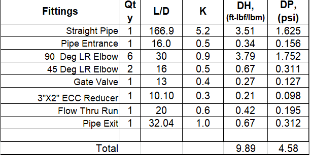
Pipe Suction Line Pressure Drop


Suction_Line_Pressure_Drop_tgkb7m.png


Suction Vessel Pressure,P1 = 0 psig

Suction Vessel Liquid Head,Z1 = (5-1) = 4ft
= 1.851 psi

Suction line pressure drop,DP1 = 4.58 psi

Pump Suction Pressure, Ps = (P1 +( Z1*RHO/144) -DP1
= 0+1.851-4.58 = -2.729 psig
= 11.971 psia

Pvap = 8.38 psia

NPSHA = (Ps - Pvap)*144 / RHO = (11.971-8.38)*144 / 66.646
= 7.75 ft

NPSHR = 6 ft

So even with 5 feet of liquid level in the tank the NPSHA is just 1.6 feet more than NPSHR. As said
by georgeverghese atleast a 3 feet of margin is required. So there is no point in increasing the minimum liquid level alarm. At 65 Deg C I find the NPSHR reduction is just 0.25 feet per Fig. 10-25 in Perry.

With the suction pipe as 3" Sch 10 pipe NPSHA increases to 11.85 feet even with 1 feet as the liquid level in the tank. This is the minimum possible liquid level. The normal tank level is 13.58 feet though. I wanted the pump to be sized for the worst condition also.

Thanks and Regards,
Pavan Kumar


I stand corrected from my earlier post - the vapor pressure of your water is problematic.

If you are not 100% settled on a pump, I would recommend looking up trash pumps - such as Gorman Rupp. They are really sturdy pumps that can pass large solids and self-prime up to 20’ or so. That way you could run a 3” line and possibly handle any upsets. I’ve used them before and they do a bang-up job with handling all sorts of gunk that comes through. They also automatically degas, if that is an issue with your wastewater.
 
Glancing through this calc, pls correct discrepancy on pumping liquid temp and corresponding vapor pressure - is it 65degC or 85degC?
 
Hi georgeverghese,

The maximum pumping temperature is 85 Deg C. We normal see 65 Deg C but sometimes the temperature can go up to 85 Deg C.
I am sizing the pump for rated condition.

I want to know how do you perform pressure drop calculation for a fitting. I found equivalent length method mentioned in Crane TP to be convenient. I just wanted a reference on how you do pressure drop calculations. If this is ok I will use further to all my calculations. Your comments will be very helpful.

Thanks and Regards,
Pavan Kumar
 
My estimates based on your viscosity of 10cP
Str length of pipe approx 25ft
Eqvt length of fittings 25ft
Line velocity 6.6fps, Darcy friction factor 0.03
Total dp 2 psi with Crane Ft correction, 2.5psi without Ft correction

How did you get total dp as 4.6psi?

Why is your viscosity 10cP - for plain water it is 0.3cP at 85degC
 
Georgeverghese, wastewater is often higher viscosity even at lower solids. He is at 12%. The wastewater that is treated at my plant would be pretty much paste at 12% solids.

Pavan, you have the wrong L/D for your fittings. 90 LR is 16, not 30, and 45 LR is 6. It appears you used short radius elbow values. Also, you’ve got to stop dribbling information out - it makes it almost impossible to actually help you.
 
Dribbling information is an understatement, what started as a pipe velocity question has turned into a major hydraulic engineering exercise with limited information.
Someone is way out of their depth with what currently appears to be an unanswerable quest.


It is a capital mistake to theorise before one has data. Insensibly one begins to twist facts to suit theories, instead of theories to suit facts. (Sherlock Holmes - A Scandal in Bohemia.)
 
Hi georgeverghese,TiCl4,Artisi,

The viscosity of 10cP is only an estimate. We have not measured it using a viscometer, which we could have done by sending a sample to a lab. I have deliberately used equivalent lengths for 90 and 45 Deg LR elbows that of short radius ones to be conservative. For r/D= 1.5 the Leq/D for 90 Deg Elbow is 14. I am not sure where I can get the value for 45 Deg LR elbow with r/D=1.5. It is not mentioned in Crane TP410.

I agree my original intention was only about the recommended pump suction and discharge velocities, which I later expanded to complete pump sizing calculation as they are all related and I am in the process of purchasing the pump in question. Pressure drop being applicable not only to pipe sizing but also to other systems such as control valves in incompressible and compressible flows, I wanted to develop a standard methodology by knowing how you do these pressure drop calculations. While the expertise on this thread has helped me a lot in expanding my knowledge and in clearing my thinking a bit, I have a lot more to learn. I apologize for dragging and dribbling the topic. I normally put forth all the information at once, but this time I happened to extend my question. With that said I think I have all the process information required to size the pump on the thread by now. If I am still missing any information I will post it asap.

Regarding the pressure drop calculation in 2" pump suction here is my calculation.

Pipe size = 2" Sch 10
ID, D = 2.157" = 0.17975 ft
Length = 25 ft

St pipe (L/D) = 25/0.17975 = 139.08

Fittings:
1. Pipe Entrance = 1, Leq/D = 16
2. 90 Deg LR Elbow = 6 , Leq/D = 30
3. 45 LR Elbow = 2, Leq/D = 16
4. Gate Valve = 1 , Leq/D = 13,
5. 3"X2" Ecc Reducer = 1 , Leq/D = 10.10
6. Tee Thru Run = 1 , Leq/D = 20
7. Pipe Exit = 1, Leq/D = 32.04

Total Leq/D for fittings = 1*16 + 6*30 + 2*16 + 1*13 + 1*10.10 + 1*20 + 1*32.04 = 16+180+32+13+10.10+20+32.04 = 303.14

Total L/D = St. Pipe L/D + Fittings L/D = 139.08 + 303.14 = 442.22

Density RHO = 66.646 lb/ft3
Darcy Friction Factor, fD = 0.0312
Fluid Velocity = 6.58 ft/sec

Head Loss, DH = fD*(L/D)* (V^2)/(2gc) = 0.0312*442.22*(6.58^2)/(2*32.17) = 0.0312*442.22*0.6729 = 9.284 ft-lbf/lbm

Pressure drop, DP = DH*RHO/144 = 9.284*66.646/144 = 4.29 psi.

All these calculations are shown in the spreadsheet that I attached above.

Please let me know if I am doing anything wrong.

Thanks and Regards,
Pavan Kumar


Okay, looks like I have misinterpreted the earlier table. I read the L/D entry on each row as the total L/D for that fitting, while you meant the L/D for one fitting. So that explains why the L/D total for all fittings in your estimate is much higher than mine. If I redo this calc on my excel sheet with your values on eqvt lengths for fittings and pipe and with viscosity at 10cP, with no correction for fully turbulent Ft for fittings, I get a total dp of 3.8psi, giving NPSHa = 10ft at 85degC. NPSHa will be more with Crane Ft correction in this case.

Pls note my interpretation of D in L/D for fittings is nominal dia, not actual ID, so D=2inch, not 2.16inch.

My mathcad sheet tells me L/D of LR 90deg elbow, 2inch = 18 per Crane and 12.2 per Darby 3-K method, while that for 45deg LR elbow, 2inch is 10.6 ft per Crane and 8.4ft per Darby 3-K method. Using these or similar values should give you more NPSH.

The L/D for the gate valve you have is only for full bore gate valve, while that for reduced bore is between 60-80, so check what type of gate valve you've got. The entry for pipe exit is not necessary, since this suction pipe exits into the suction nozzle of the pump.

 
pavan.

This is all very complex for such a small system and the reason you're having some difficulty is that at these sorts of sizes there is a massive jump from a 2" pipe to a 3" pipe which you don't get when e.g. you go from a 16" pipe to a 20" pipe.

Your 10 feet of inlet pipe looks ridiculously complex with six 90 degree LR elbows and two 45's.

Simplify this.

ALso determine if your 75 GPM is an aim or a fixed requirement. Nothing will work out exact so even a change in tank fill height could result in a change of 5-10 GPM.

So if you do 65 or 85-90 GPM is this a problem?
If not then just size your pump to meet the system curve then let it go and find the natural balance point.

But yes, check the actual power consumed at your duty point and efficiency of each different supplier as some will be a lot more than others depending on the design of the pump.

So for me go for 3" inlet and outlet pipe size and lower power demand. Job done.

Remember - More details = better answers
Also: If you get a response it's polite to respond to it.
 
Status
Not open for further replies.

Part and Inventory Search

Sponsor