Eng-Tips is the largest engineering community on the Internet

Intelligent Work Forums for Engineering Professionals

Rectangular plate; two edges simply supported, two edge free 4

Status
Not open for further replies.

IdanPV

Mechanical
Aug 26, 2019
425
0
16
IL
Hello everyone,

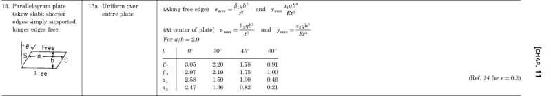
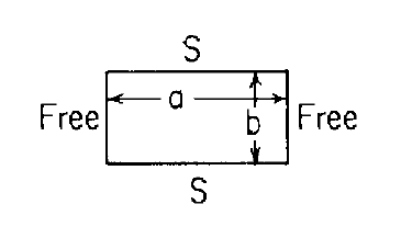
I am seeking assistance in finding formulas to calculate the stress and deflection of a flat, rectangular plate. The plate is simply supported along its long edges and free on the short edges, as illustrated in the attached figure.
Plate_avg5fi.png

I have explored resources such as Roark's and Timoshenko, but unfortunately, I have not been able to locate relevant information.

I appreciate any help you can provide.
 
Replies continue below

Recommended for you

would it deflect like a SS beam, length = b ?

"Hoffen wir mal, dass alles gut geht !"
General Paulus, Nov 1942, outside Stalingrad after the launch of Operation Uranus.
 
Not quite in detail, it is still a plate in bending (the free edges would do something interesting) but that's a good check. Perhaps at small deflections it would be the same. To that end I wonder how simply supported is defined in context does it restrain 2 dof or 3? Is the loading at the centre or uniformly distributed?


Cheers

Greg Locock


New here? Try reading these, they might help FAQ731-376
 
Thank you for your feedback.
I appreciate your comments. here is additional details that I inadvertently omitted:

Plate Thickness: The plate has a thickness of 2mm.
Material: The plate is constructed from stainless steel.
Load Distribution: The load is uniformly distributed across the plate.
Dimensions: The width (b) of the plate is 550mm, and the length (a) is 1500mm.
 
Have you looked in Roark?

-----*****-----
So strange to see the singularity approaching while the entire planet is rapidly turning into a hellscape. -John Coates

-Dik
 
Hi,

As I wrote in my first post, I tried to find information in Roark's (Chapter 11 and Table 11.4) but didn't find any.
 
How thick is the plate relative to its width(b) and length(a)?

The cross-section of this configuration, looking along the axis of the long direction, would be a equivalent to a 'Simple Beam with a Uniformly Distributed Load'. The length (dim 'a') only comes into play when computing the Moment of Inertia (I). Once you've calculated that (which is why we need to know how thick the plate is), all you need to know is the total weight of the plate and the Modulus of Elasticity (E) (Young's Modulus) of the material, you should have all you need to calculate the maximum deflection and maximum stress.

John R. Baker, P.E. (ret)
Irvine, CA
Siemens PLM:

The secret of life is not finding someone to live with
It's finding someone you can't live without
 
Does this help? for angle = 0?

Clipboard01_pdbo3h.jpg


-----*****-----
So strange to see the singularity approaching while the entire planet is rapidly turning into a hellscape. -John Coates

-Dik
 
I found this example in Roark's but in this case, the shorter edges are simply supported.
I'm curious if this scenario is more conservative than mine
 
I think there’s a part in Roark that shows you how to modify beam bending by introducing Poisson’s ratio effect. The free edges do deflect differently to the main section, down to the fact that there is no distributed shear or moment along the edges.
 
Roark Seventh Ed. said:
11.10 Bending of Uniform-Thickness Plates with Straight Boundaries
Formulas. No general expression for deflection as a function of position in a plate is given since solutions for plates with straight boundaries are generally obtained numerically for specific ratios of plate dimensions, load location, and boundary conditions.

The sub-section titled "Bimetallic Plates" (11.4 in the Seventh Ed.) presents a method that might simplify to your case.
 
IdanPV, Your error is in your problem statement. You don't have a "plate". You have a simply supported beam of "b" length, "a" width, and thickness of 2mm.
 
like the first reply says ?

"Hoffen wir mal, dass alles gut geht !"
General Paulus, Nov 1942, outside Stalingrad after the launch of Operation Uranus.
 
and of course the limits of this would be something like deflection < thk/2 (or thk/n, n>1)

depending on the edge in-plane support. Are the edges free to rotate and translate ?

"Hoffen wir mal, dass alles gut geht !"
General Paulus, Nov 1942, outside Stalingrad after the launch of Operation Uranus.
 
I'd consider it as a plate... just based on geometry...

-----*****-----
So strange to see the singularity approaching while the entire planet is rapidly turning into a hellscape. -John Coates

-Dik
 
depends on thickness. very quickly these can become large displacement structures, with out-of-plane loads reacted by membrane loads.

"Hoffen wir mal, dass alles gut geht !"
General Paulus, Nov 1942, outside Stalingrad after the launch of Operation Uranus.
 
All I remember is something about "plane sections remain plane" as an assumption for Euler Bernoulli beam theory.

...I remember those words but at this moment I don't really remember the meaning (it probably equates to whatever it is that rb1957 said!)
 
ok, I remember less about the electrical stuff I "learnt" ...

"Hoffen wir mal, dass alles gut geht !"
General Paulus, Nov 1942, outside Stalingrad after the launch of Operation Uranus.
 
Status
Not open for further replies.
Back
Top