Eng-Tips is the largest engineering community on the Internet

Intelligent Work Forums for Engineering Professionals

  • Congratulations waross on being selected by the Tek-Tips community for having the most helpful posts in the forums last week. Way to Go!

Reduce Stiffness 1

Status
Not open for further replies.

cirokos

Civil/Environmental
Apr 11, 2022
63
0
0
GR
Hello everyone,

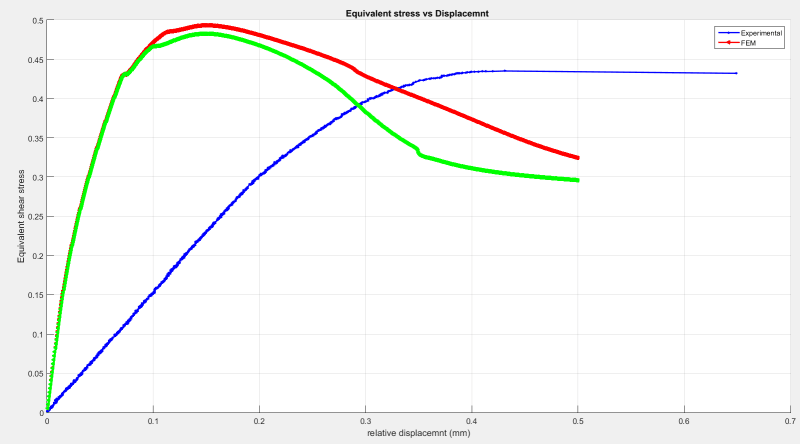
I am running a nonlinear analysis with imperfections included by an eigenvalue buckling analysis with a factor of 0.1-0.5 ( the max dmx from buckling analysis is 1 , units are N/mm ) but the stiffness is much higher than the experimental results. How can I reduce the stiffness in order to match the experimental?

Any tips would be really helpful.

Screenshot_2022-11-24_011211_kils9f.png
 
Replies continue below

Recommended for you

Can you share some details regarding the settings of the analysis ? Screenshots of the model with boundary condition/load symbols will also be helpful.
 
Yes, it is for the hex core model. The displacement is measured from the crosshead of the machine.

I haven't done any hand calculations about the stiffness. Should I make the BC less rigid?

FEA way
you can find in a previous post of mine.
 
Greglocock,

So, if I understand correctly you think the magnitude of the load is the problem?

I will take a better look and see if I can make changes at how the load is applied and BC.
 
That's not what Greg wrote ...
"Your load is in the ballpark, your stiffness is not."
and ...
"Therefore your model seems to have a fundamental error,"

he didn't say
"the magnitude of the load is the problem".

"Hoffen wir mal, dass alles gut geht !"
General Paulus, Nov 1942, outside Stalingrad after the launch of Operation Uranus.
 
Do you have any idea regarding how the imperfections in the model matches the test object?

Your FEM-model is several times stiffer than the test object. I would try an analysis without imperfections and see what effect the imperfections have. I would also ensure that the comparison for deformations are relevant.

I don't think you should change anything until you have checked FEM setup vs Experimental setup. Differences?
 
For many test setups, cross head displacement is a near useless measurement. There is often flexibility in the test machine, test fixture, etc. which is not in your model. You need to compare the model to displacement measurements on the test specimen at the exact same locations.

If you post photos of the test, and pictures of the FEM indicating where you are extracting displacements, we might be able to help more.
 
I did a study to see how imperfections affect the structure. I took the results from an Eigen Buckling analysis and updated the geometry with the first buckling mode, after that, changed the values of the scale factor to see how they will affect the curve.
the results show a significant drop in the force and stiffness but still not a -perfect- match.

Regarding the boundary conditions, most literature I found uses the same boundary conditions, so cannot say for sure if they are the problem.
 
The problem is not in what idealized boundary conditions the literature applies in a FEA model (I'm not convinced that your case is a widely used FE benchmark problem though), but in what boundary conditions the experimental setup actually contains. Stiff, pinned and complete fixity against rotation are almost never achieved in practice.

Did you figure out spring constants (linear or non-linear) of the supports in your experiment while using the bare minimum of ideal (pin, clamped) boundary conditions to prevent rigid body motion? If not, your model is probably too stiff, and based on the first result you posted it seems that this is the case.
 
I haven't applied spring constants (not very familiar with how they are applied), in my model I used boundary conditions (BC) to simulate the loading plates. The applied BC used to output a perfect shear loading without rigid body motion and deformed shape matched well with the experimental one.

Could you elaborate on the spring constants idea?
 
it sounds to me like you're applying BC to the model that are infinitely stiff or flexible (prevent any displacement is some direction or have zero stiffness).

I think the idea is to put a finite stiffness spring between your model and the infinite stiffness of a hard constraint.

I'd keep 6 rigid (infinitely stiff) constraints to satisfy rigid body motion.

"Hoffen wir mal, dass alles gut geht !"
General Paulus, Nov 1942, outside Stalingrad after the launch of Operation Uranus.
 
yes, the applied bc simulates a rigid connection.

Rigid body motion is satisfied. I am not quite sure how I could implement the idea you suggest.

Adding a real constraint to simulate some kinda of stiffness?
 
you have rigid constraints ... you constrain a node of your model. The model node cannot deflect, not even 1nm.

for finite stiffness constraints, you put a CBUSH (spring) between the model (node) than the constraint (node). Now the model node has the ability to deflect slightly.

"Hoffen wir mal, dass alles gut geht !"
General Paulus, Nov 1942, outside Stalingrad after the launch of Operation Uranus.
 
Okay okay, I get it now. I will try to find how to implement that in my model and see the results.
Thanks a lot!
 
No, no, no, this is for a model of honeycomb core presumably bonded to thick steel plates for core shear tests. The bond of the core to the plate is quite close to rigid. However, the FEM results are being compared to test machine deflections, per OP comment above. This is likely the source of the error - see my earlier comment. The test data is likely the problem, not the FEM.
 
"The test data is likely the problem, not the FEM." ... ? data's data, it can't be wrong.

It may not be what we think it is, it may be that our means of collecting it has disturbed it. But certainly the way the FEM is modelling the test is at fault (at variance with what it's trying to represent).

Whether correctly modelling the test is valid for the real work, that's a different question.

"Hoffen wir mal, dass alles gut geht !"
General Paulus, Nov 1942, outside Stalingrad after the launch of Operation Uranus.
 
Status
Not open for further replies.
Back
Top