Eng-Tips is the largest engineering community on the Internet

Intelligent Work Forums for Engineering Professionals

Regarding Lateral Torsional Buckling 1

Status
Not open for further replies.

allimuthug

Civil/Environmental
Oct 5, 2014
142
0
0
CA
Hi Everybody,

I have a channel simply supported between the columns as shown in the figure attached. The channel is connected to the column flange by a shear tab or fin plate.
LATERAL_TORSIONAL_BUCKLING_eqlsqn.png

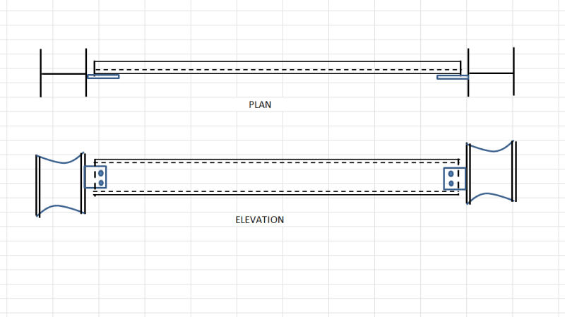
(i)As per AISC 360-05 clause F1 "The provisions in tis chapter are based on the assumption that the points of support for beams and girders are restrained against rotation about their longitudinal axis" It means the fin plate or the shear tab should be restrained against rotation or should have torsional capacity ?
(ii) It the fin plate doesn't have any torsional capacity this AISC 360 is no more applicable to the channel since it doesn't quality the assumption of AISC?
(iii) How much is the torsional rotation the fin plate is subjected to?

Please clarify me I am totally confused, because if this doesn't work then the whole world cannot use fin plate connection at all.
 
Replies continue below

Recommended for you

Well You need to calculate the stiffness or rotational capacity of your connection.
it can be
1)stiff
2) soft
3) or something in between depending on the geometry parameter
 
I would consider this condition to provide effective rotational end restraint to the channel. You can use the bracing chapter of AISC to evaluate the strength and stiffness of the shear tab if you are so inclined.

I like to debate structural engineering theory -- a lot. If I challenge you on something, know that I'm doing so because I respect your opinion enough to either change it or adopt it.
 
Not knowing the AISC provisions, I could be way off, but here goes: I suspect it's simply saying that whatever you connect the beam to (the fin plates in this case) have to be stiff enough not to twist substantially, in order to assume the unbraced length of the beam for lateral torsional buckling to be the distance between the connections; in this case center to center distance between the bolts. Otherwise, your unbraced length has to be measured to the connections of the fin plates to the columns. If your sketch is to scale, without some advanced analysis, I would go to the faces of the columns for the unbraced length.
 
i have also considered the exact same question but have always assumed the beam is restrained against ltb. if the beam is free to twist at one end, the critical load decreases significantly, but on the other hand you have the same connection at the other end, so you cannot easily calculate the critical moment (you have to give each connection a rotational stiffness). the equations in the aisc i assume are similar to the ones in Europe, they consider the beam restrained.

i guess the same idea is applicable to supported i beams. im also quite interested in other people s thoughts. is kootk on the mark (as quite often in my opinion)?
 
Eaglee said:
is kootk on the mark (as quite often in my opinion)?

Thanks for that. I don't know how much of an attempt has been made to draw things to scale here but, at the proportions shown, this doesn't look much different from AISC's extended shear tab connection which is routinely assumed to provide rotational restraint to the ends of supported beams. Obviously, there are limits. If our connection tabs here were, say, 16 ga cold formed steel, we'd be having a very different conversation.

In cases where I've questioned the rotational restraint provided by a shear tab, I've sometimes replaced the tab plate with a short length of channel. I feel that would beoverkill here based on the information provided however.


I like to debate structural engineering theory -- a lot. If I challenge you on something, know that I'm doing so because I respect your opinion enough to either change it or adopt it.
 
For the case presented (assuming it is fairly well to scale), there is very little difference between using an an unbraced length that's C-to-C of the bolted connections and going to the faces of the columns. If it's failing just slightly in LTB using the length between the faces of the columns, then it may be time to 'sharpen the pencil' and analyze the torsional resistance of the shear tabs to justify shortening the unbraced length a bit, otherwise why expend the effort for no benefit?
 
HotRod touched on one way to think about it in his first post, and I concur with his second one.

If you consider the "beam" to extend from column to column, with most of the cross section being the channel, and a small zone at either end with a reduced cross section (shear tab), you can compute the lateral torsional buckling capacity for that "beam".

If you then rotate that "beam" to vertical, call it a column, it looks a lot like a stepped column like those you find in some industrial applications. And for stepped columns of many reasonable proportions, the zone with reduced cross section at either end turns out to have very little effect on the buckling behavior of that stepped column.

In summary:

[ul]
[li]I think that you can reasonably consider the "beam" braced against LTB with an unbraced length from column to column.[/li]
[li]I think it's plausible, depending on the proportions of the shear tabs, that those tabs really do provide the stiffness to consider an unbraced length from bolt line to bolt line -- but it's probably not often economical to sharpen the pencil that far.[/li]
[li]And I think some engineers probably do the latter without putting any specific numbers into the stiffness of the tabs, and get away with it because it's close enough to the truth for our line of work.[/li]
[/ul]

----
The name is a long story -- just call me Lo.
 
Lomarandil said:
And I think some engineers probably do the latter without putting any specific numbers into the stiffness of the tabs...

Some engineers? This is truth space so I'm going to be a little more aggressive in ensuring that the truth gets out here. It's absolutely my impression that effectively all engineers do this. And frankly, the ones that don't should either seek some additional mentoring or hang it up and stop wasting society's precious resources. This is an interesting thing to talk about but nobody in practice ought to be looking at this as a routine check needing to be performed.

HotRod10 said:
Otherwise, your unbraced length has to be measured to the connections of the fin plates to the columns.

lomarandil said:
If you consider the "beam" to extend from column to column, with most of the cross section being the channel, and a small zone at either end with a reduced cross section (shear tab), you can compute the lateral torsional buckling capacity for that "beam".

Before I dive into this, I'll reiterate that it is my opinion that there's nothing worth checking here. All that follows is just theoretical clap trap.

I believe that the approach advocated in the two, previously quoted statements is flawed. It assumes that the shear tab can be considered a torsional extension of the channel. I take exception to the approach based on the following:

1) Warping stiffness is an important part of the channel torsional stiffness and therefore and important part of LTB. And warping stiffness cannot reasonably be transferred to a knife plate, particularly through a bolted shear connection. In this sense, the correct analogy here is a stepped column with a hinge at the step.

2) Obviously, some measure of torsional stiffness can be transferred through the connection, through the knife plate, and in to the column. A bit of Saint Venant etc. In the highly unlikely event that this exercise would be worth the effort, it would require a complex modification of our standard LTB equations. Frankly, I challenge anybody to propose the specifics of just what that modification ought to be. I have pretty strong theoretical leanings and I can just barely understand the normal LTB derivation.

3) Because a modified LTB approach is intractable, I think that it's erroneous to suggest that one might easily deal with this by simply taking the LTB length to be the face of column to face of column distance. It's the furthest thing from simple and would really be trending away from things that have been validated through testing in the past.

I like to debate structural engineering theory -- a lot. If I challenge you on something, know that I'm doing so because I respect your opinion enough to either change it or adopt it.
 
After a long research I got the answer.The direct answer is given in Euro code(Joints in steel construction SIMPLE JOINTS TO EUROCODE 3), please find the references below.
Thank you every body.
EC-CONN-1_u6eow9.png

EC-CONN-2_zarlwb.png

EC-CONN-3_tkquhs.png
 
You're right, I was hedging my words too much.

I expect that in typical applications and proportions, practicing engineers will consider it OK by inspection. What I should have said was that some engineers will consider it OK by inspection regardless of proportions -- and that's where the approximation can be saved by other factors.

To get down into the clap trap with you:
1. I can't think of any common bolted connection that would create an effective warping restrained end condition for a channel -- so isn't this a moot point?

2. Absolutely, I am not suggesting any robust approach. If it's ever, ever justified to consider it, I would only apply approximations and rules of thumb. Going from a 5 second "eh, OK by inspection" to "I've actually inspected it for 5 minutes, and it's OK".

3. I suppose this point is predicated on how we settle #1.

edit: Thanks for the follow up allimuthug!

----
The name is a long story -- just call me Lo.
 
lomarandil said:
1. I can't think of any common bolted connection that would create an effective warping restrained end condition for a channel -- so isn't this a moot point?

In my mind, this fact alone almost completely invalidates the approach of considering the shear tab as a torsional extension of the main member for LTB. All you'd be left with is whatever St. Venant stiffness would get you (not much in a channel). So I'm seeing this as pretty relevant to the discussion of whether or not this non-issue could be addressed by simply considering a longer beam span for LTB. How are you seeing this?

I like to debate structural engineering theory -- a lot. If I challenge you on something, know that I'm doing so because I respect your opinion enough to either change it or adopt it.
 
KootK, I'm confused by what you seem to be suggesting here. I'm getting that you're saying the effective unbraced length is actually slightly longer than the face-to-face column distance (I think I understand how you get there and I agree). However, at the same time you seem to be advocating using the shorter length of the C-to-C of the connections. If I've understood you correctly on both counts, it would seem that using the face-to-face of columns would be closer to the actual behavior, and more conservative than what you're advocating. If that's the case, why are you seemingly against using the longer unbraced length?
 
HotRod10 said:
I'm getting that you're saying the effective unbraced length is actually slightly longer than the face-to-face column distance

Certainly, it was not my intention to say that. I feel that the unbraced length is the bolt line to bolt line distance. Unless I was desperate, however, I probably would have just taken it as the column flange to column flange distance or even the column centerline to column centerline distance. Regardless, my opinion is that exaggerating the unbraced length of the channel is not a valid procedure for compensating for the torsional flexibility of the connection. Unless one wants to get super fancy, I think that the tab needs to be evaluated as a stand alone torsional bracing element, either by inspection or by AISC procedures for bracing requirements etc.

Does that clear my position up at all? I'd like to at least be internally consistent with myself.

I like to debate structural engineering theory -- a lot. If I challenge you on something, know that I'm doing so because I respect your opinion enough to either change it or adopt it.
 
I think we're getting a little off-track with the discussion of whether to use the face-to-face distance or not.

The original question is a very valid one. Section F.1 of the spec requires restraint of rotation at beam supports, but doesn't go into any more detail. A simple answer I've come across is in the April 2010 issue of Modern Steel Construction:

It is common practice to provide a connection with depth at least equal to T/2, as recommended for all the framed connections in Chapter 10 of the AISC Manual, to ensure that the proper restraint is provided. It may be possible to provide the required restraint by other means, but the half-depth connection has become a de facto requirement.​

Now to get into more detail, Section 5.2.11 of the Guide to Stability Design Criteria for Metal Structures" states

"End connections such as partial end plates (Lindner, 1985) and coped ends (Yura and Cheng, 1985; Cheng et al., 1988; Cheng and Yura, 1988; Lindner, 1994) can influence the LTB resistance substantially. The influence of end copes should be
considered when the depth of a cope is greater than or equal to 0.2d, where d is the total depth of the cross section. Coped ends may be reinforced to offset this reduction in the LTB strength."​

I also just found a paper titled "Buckling of coped steel beams and steel beams with partial endplates" by Johan Maljaars that I'd like to give a thorough read.

So my approach right now is to make sure that my connections have a depth of at least T/2 and watch out for the following situations:
- large span/depth ratio
- member near capacity
- thin webs
- deep copes
- thin or extended shear tabs
 
Your response clarifies your position, KootK. I'm not sure that clears up my confusion as to the justification for your feeling "that the unbraced length is the bolt line to bolt line distance", which would, by your subsequent statements, be an assumption yielding a higher LTB resistance than we agree a detailed analysis would show for common connections of that type. Are the LTB calculations inherently conservative? It wouldn't surprise me if they were, but I haven't delved deeply enough into those mechanics to know. I'm not trying to be contentious; just interested in broadening my perspective.
 
In regard to the original question posed in the OP, "It means the fin plate or the shear tab should be restrained against rotation or should have torsional capacity?"

I think the answer is fairly clear in the text in question: "...rotation about their longitudinal axis..." is clearly referring to torsional rotation of the beam.

The discussion then moved to attempting to answer parts "ii" and "iii" of the OP, regarding the torsional restraint (or lack thereof) of fin plates, and we're still there.

The referenced provision from the Guide to Stability Design may add some fodder for discussion, but doesn't directly address or resolve the debate at hand.
 
For the sake of simplicity I'd liken it to wood, see TR14, simply saying the plates don't provide enough torsional restraint/stiffness to act as a point of LTB restraint and extending the unbraced length of the beam to the column flanges or centerlines may not be enough. From TR14 for a solid rectangular wood section the effective length for LTB can be nearly 2x the span length.

Open Source Structural Applications:
 
Status
Not open for further replies.
Back
Top