Continue to Site

Eng-Tips is the largest engineering community on the Internet

Intelligent Work Forums for Engineering Professionals

  • Congratulations KootK on being selected by the Eng-Tips community for having the most helpful posts in the forums last week. Way to Go!

Regenerative brake 3

Status
Not open for further replies.

Sajuuk

Industrial
Jul 13, 2020
2
Hello,

I know some basics about electric motors (sync, async, DC) but i know nothing about regenerative braking used in some cars (e.g. hybrid or fully electric).

I read on wikipedia that it is not (yet) possible to completely and safely stop a vehicle only by using it and a manufacturer still needs brake pads.

Is it really the case ? Where can I find some research on this ?

Could it be possible with the right electronical system ?


Thanks for your answers :)
 
Replies continue below

Recommended for you

Thank you Curt for confirming my understanding.
A couple of questions:
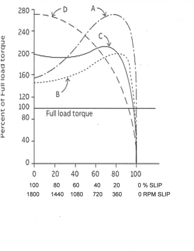
Are the torque curves of induction motors in electric vehicles similar to any standard industrial motor curves?
Further to this statement:
Curt said:
This limits the slip to the right-hand end of all of the torque curves you show, between the non-load torque and the breakdown torque.
If I start with the curves that I have posted and first, change the index from percent to RPM, with 1800 RPM being 100%.
Now, if I reverse the index so that 1800 RPM is on the left end and 0 prm is on the right end,
and
Last, I relabel the diagram from Percent of no Load Speed.
To
RPM of Slip
Now is this still a valid chart.
And, If we use only the portion between breakdown torque and Zero RPM Slip, is this valid for all speeds except very low speeds.
I find this an easy way to understand and explain VFD characteristics.
Yes, I understand that at very low speeds the accuracy may suffer, but is the accuracy valid for speeds above about 40 RPM to 80 RPM, for a 1760 RPM rated motor?
I understand that the relationship between slip RPM and torque and current holds up at all but very low speeds.
Thanks.

Bill
--------------------
"Why not the best?"
Jimmy Carter
 
HERE IS THE FIRST STEP IN RE-LABELING THE CURVES
SLIP_CURVES_5_ct3rag.jpg


Bill
--------------------
"Why not the best?"
Jimmy Carter
 
Dynamic braking is done by using the motor as a generator or taking energy out of the motor.

From the motor perspective, it is always dynamic braking regardless of where the energy goes. Doesn't much matter though because the motor itself can't run or brake unless it's connected into a control system of some sort.

From a motor plus motor control system perspective, regenerative braking is used when the energy is fed back to the power source. Dynamic braking is typically used as the description when the energy is dumped as heat in resistors, but if you want to go more historic then rheostatic braking can be used. I'd consider theostatic braking more appropriate when the stator gets connected directly to the resistors and the motor field is controlled, AKA DC traction motor locomotives.

DC Injection braking is not dynamic braking because the motor is not acting as a generator. All the load stopping energy plus the heating from the injected DC is dissipated in the motor.

No modern EV is using an induction motor, so what's the point of making this thread about induction motors in EV's?
 
Bill:

You've done exactly the transformations I recommend to people trying to understand field-oriented control of induction motors. I almost put these in my last comment, but didn't have the time. I would go one step further and express the slip in Hz as well as RPM.

The next step is to create the generator portion of these curves by rotating the motoring curves you show by 180 degrees about the zero-slip, zero-torque point. Now you have the essentially linear parts of the torque/speed curves covering both the motoring and generating zones.

In direct-off-line (DOL) operation, if the actual load torque changes, the motor accelerates or decelerates, moving on the curve until generated torque matches the load torque. This is true for both motoring and generating. All normal operation is in the approximately linear (monotonic, at least) zone. In the generating zone, it is returning energy directly to the AC lines.

In the field-oriented control (FOC) used in EVs, the controller takes the desired generated torque level (plus or minus) and calculates the slip frequency required to create this torque. The controller needs to know the "slope" of the particular motor's torque speed curve. This slip frequency is then added to the mechanical frequency to get the net electrical frequency to be applied. (This calculation is typically updated thousands of times per second.)

You ask: "If we use only the portion between breakdown torque and Zero RPM Slip, is this valid for all speeds except very low speeds?"
If you can actually measure the speed, especially with a position sensor such as an encoder or resolver, this is valid for all speeds INCLUDING very low (and zero!) speeds. People have used FOC induction motors as positioning servos for over 30 years now.

If you try to calculate the speed from electrical properties, the quality of the estimation degrades at lower speeds (when the back EMF is small compared to various noise and disturbance effects).

With (closed-loop) FOC, you have a constant "direct" (inducing) current magnitude -- at least until you get to base speed -- that is parallel to the instantaneous rotor field orientation. This is typically about 10% of the maximum possible value. You have a variable "quadrature" (torque-producing) current perpendicular to the rotor field, which is in-line with the back EMF in the phases. So to produce this current, you need to command a voltage that is V = EMF + I*R.

The total voltage is the vector sum of these two perpendicular components. At high speeds, the back EMF dominates, so the total voltage magnitude is closely proportional to speed. But at low speeds, the perpendicular voltage to create the direct current has a significant contribution to total magnitude. But the nature of the FOC algorithm handles this effortlessly.

However, with open-loop VFDs, if you want any reasonable low-speed control, you must include this effect in your magnitude calculations. A constant Volts/Hertz ratio can be close enough at higher speeds, but you need a "boost" at lower speeds to provide the inducing current.

Curt Wilson
Omron Delta Tau
 
Status
Not open for further replies.

Part and Inventory Search

Sponsor