Continue to Site

Eng-Tips is the largest engineering community on the Internet

Intelligent Work Forums for Engineering Professionals

  • Congratulations KootK on being selected by the Eng-Tips community for having the most helpful posts in the forums last week. Way to Go!

Reinforce or Replace Existing 6x8 Wood Beams in Basement 1

Status
Not open for further replies.

mfstructural

Structural
Feb 1, 2009
229
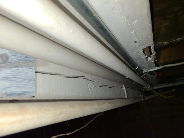
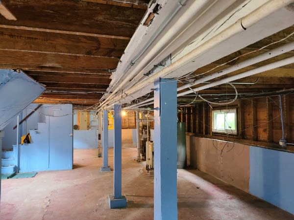
Hey everyone, curious on getting other people's input on this one. I looked at a wood beam/column system in a basement not too long ago, the beams were visibly sagging a bit and exhibited checking of the wood. I would not characterize the splits as due to tension stresses. Furthermore, the splits were about 1 inch deep on only one side of the beam. I am thinking this can be reinforced by added a steel angle under each bottom corner and either lagging it to the beam or support it on angles at the ends of the beam. the angles supporting the beam angles would be mechanically fastened to the column. I had debated on added a thin steel plate, maybe 1/4" to each side of the beam but I wanted to avoid through bolting through the checking in the beam. I am working with the homeowner to try and reinforce since it may be cheaper than replacing everything....especially since there are pipes and conduit along and near the wood beams. I've included some photos so you have reference.
e032b753-088a-4582-b081-93c0f898296f_x4ocel.jpg
f37da63c-806f-4348-a332-5cfe08215895_hg32tv.jpg
2039137c-9e6f-4b2e-8921-a40b678caebe_kn9e9v.jpg
4ba7f6e7-0175-4897-8922-03dc7a7538af_rvigup.jpg
 
Replies continue below

Recommended for you

I have some questions first.

1. Is the 6x8 turned strong direction up or weak direction up?
2. Are the splits you are concerned with in the compression portion or tension portion. The pictures look like compression side if the beams are simple span.
3. Do calcs indicate the beams are sagging more than they should for the given actual load?
4. Do you think the beams are overloaded for strength?
5. were the checks and splits accounted for in the lumber grading? Most likely not.
 
mfstructural,

The checking shown in the photographs looks like standard drying checks. Have you stretched a string from one end to the other and verified that the sagging per each section is unacceptable??? What are your limits??? What are you estimated design loads??? As others have commented it doesn't look like excessive sagging.

Jim


Thanks for the questions. I should have included some of that. Calculations show that the beam is 80% overstressed. The beam is 7.5"H x 5.5"W. There is a wall above the beam that is carrying the second story also, tributary width carried is 11'. When I run those numbers, using Fb=1500, the beam is overstressed as stated above and the deflection is calculated at .53". The sagging of the beam was about an inch at a couple of the spans. My thought was because it's overstressed, I am planning to reinforce or replace simply based on calculations to avoid any issues down the line. The client wants to finish the basement and I don't want to have any calls down the line. The checks in the beam are in the top (compression) section of the beam. I'm using 10 psf DL and 40 PSF LL per floor for a total of 100 PSF.
 
Well, to get the spitballing going, what about the possibility of bending a plate to make a U-shaped and sliding it up from underneath. It may require some welding or fabricating in pieces that have to be welded before installation. I do not think the fastening of the vertical legs would have to be through bolted. The vertical legs would have to be stabilized to prevent buckling. The big question here is what is your moment and shear over the column?

Putting 4 angles at the corners as you mentioned may work but are you counting on them acting a 4 separate angles or some composite section? If you cannot make it work as a composite, you cannot take advantage of the Ad^2 part of the formula.
 
Can't you add some more columns instead? The access past the existing ones is already pretty bad, so might be the least worst option.

Or sister the beam and add a bit more to the existing columns to take the load?

Remember - More details = better answers
Also: If you get a response it's polite to respond to it.
 
Getting composite action from your angles is probably out of the question, but you could easily put some honkin' angles just on the bottom of the beam that should be able to carry all the load. Something with an un equal leg, you can just screw the vertical leg to the beam to get your Lb down. I think that approach would work pretty good, you'll need to dream up something to attach to column but seems reasonable to me.

Another idea might be to flank one or both sides with LVLs and add trimmers to the post.

A flitch plate beam comes to mind as also quite simple, but you don't want to through bolt so that wouldn't work.

Question: Is deflection already past allowable limits? Would you instruct the installer to jack the existing beam before adding the reinforcement?
 
I agree with LittleInch. Columns or a wall designed into the space may be a better solution.

In your bottom right picture, the columns look like they have a noticeable lean to them. Looking at the angle of the column relative to the light blue line at the top of the wall indicates they are. I rarely say this but I think your client needs to consult with someone on the paint colors. My father was retired Air Force. Looking at that light blue makes me feel like I am in base housing from the 60s again.
 
Thanks for the thoughts. I thought about the extra columns or LVLs on the sides but there is limited room. What is everyone's thoughts here on adding a plate to each side? I'm thinking a 3/16" plate could be sistered to each side and through bolted. I was tryong to avoid drilling through the checking, but maybe the checks can be infilled with an epoxy? Of course the ulimate decision would come down to cost to do the work compared to an angle or replacing everything.
 
This seems a reasonable application to look into Carbon Fiber strips or wrap. That will improve the strength, but does not add much stiffness. Sika CarboDur or Simpson can help. They would need to strip the paint, but that is not too bad so long as you do not have any lead. I see a lot of site constraints that will make replacing or adding thick members very problematic.
 
A bunch of acrows?

Pretty simple and cheap.

Remember - More details = better answers
Also: If you get a response it's polite to respond to it.
 
80% is a lot for that beam to be overstressed to be honest. I've rarely come across old construction like that where they're drastically deficient. A hair over, sure that happens, but 80% is extreme. It's possible they ran it as spanning from outer bolt to outer bolt. Would it be more cost effective to provide some column capitals to shorten the beam span? Are you sure it's simple span as well? Many of these old beams were a 40 foot long single piece. Moment's would be reduced if that were the case.
 
I like your original idea of angles on either side. Should be cheaper to purchase and install than carbon fiber, and the bent u-plate doesn't add much to the angle solution in my opinion. I'd be less than pleased putting up a bunch of posts if it was my basement. You can occasionally fasten the angles to the beam to try and prevent buckling, but I don't think LTB buckling is actually possible if the angles form a U.
 
How did you determine the species of wood and arrive at Fb = 1500 psi? The 80% overstress is highly dependent on the species of wood.

Next, do you plan to remove the sag or live with it? If so, how do you plan to remove it? Sometimes jacking an older structure will cause more problems than it solves (especially with cracking of lath and plaster walls).

If you are concerned about the checks becoming larger, you can add a belt and suspender system. Drill a vertical hole through the section of beam where the checks or splits are located. Run a threaded rod through the hole and place a small plate and nut on each side. That will clamp everything together and minimize the chances of it getting any worse.
 
Are the beams continuous? That would bring the apparent overstress down considerably.
 
The beam being overstressed based on my calculations was surprising to me also. I have not had that occur often with these older timber beams. I don't know the strength of the wood and made an assumption. Any thoughts as to a more appropriate way of estimating Fb? It's a hardwood, home is about 100 years old.

The beams at two of the 5 post locations are continuous. the rest are simply supported, single span.

I don't plan on removing the sag. The homeowners are ok with it, and jacking it up will cause more damage to all the interior finishes. They are ok living with the sag as it is, even another 1/2" or so, but don't want to deal with more than that. I'm thinking about reinforcing because the beam is coming up as overstressed, and it's sagging.

So the main question is whether to support by adding another column, angles, or plates to the sides. Has anyone ever through bolted a beam like this with checking to add reinforcing plates?
 
If you reinforce the beam without partially lifting some of the sag out before attaching the reinforcement, how do you reduce the stress on the existing beam? The new reinforcement would only take its share of any new loads. The already overstressed wood beam would still take additional load based on its EI.
 
Status
Not open for further replies.

Part and Inventory Search

Sponsor