Continue to Site

Eng-Tips is the largest engineering community on the Internet

Intelligent Work Forums for Engineering Professionals

  • Congratulations SSS148 on being selected by the Eng-Tips community for having the most helpful posts in the forums last week. Way to Go!

Reinforced Concrete Retaining Wall - Specifications for expansion joints? 1

Status
Not open for further replies.

kellez

Civil/Environmental
Nov 5, 2011
276
Hello everyone, i am designing a reinforced concrete retaining wall (please see details on the drawings below)
and i would like to know what type of expansion joints do i need to use on the stem and at what spacing?

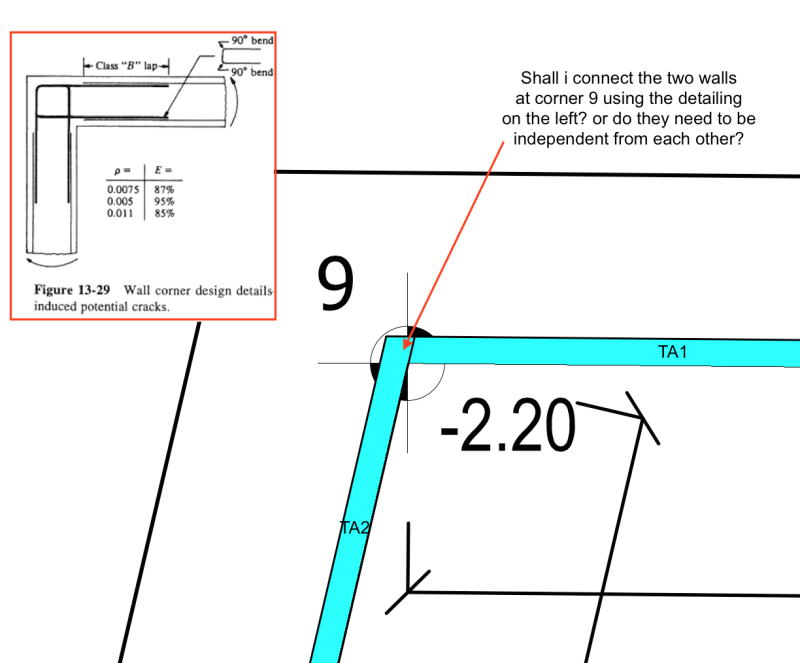
1) My main question now is, is it necessary to divide the wall into different sections along its
length by stopping the distribution bars and installing an OSB board together with an insulation board?
(see picture below: picture doesnt show the OSB and insulation board but shows that the distribution bars are discontinued)

CYA672B.bmp


2) or is it ok to just create a v-groove shape along the full height of the stem wall, by fixing one long plastic piece inside the formwork?
in addition you could also cut every other distribution bar at this location to weaken the stem at this location and promote the cracking there

3) and the last option is to cast the wall normally and then sawcut along the full height of the stem, in addition you could also cut
every other distribution bar at this location to weaken the stem at this location and promote the cracking there

which one is the best approach and is it possible to avoid dividing the wall into sections?


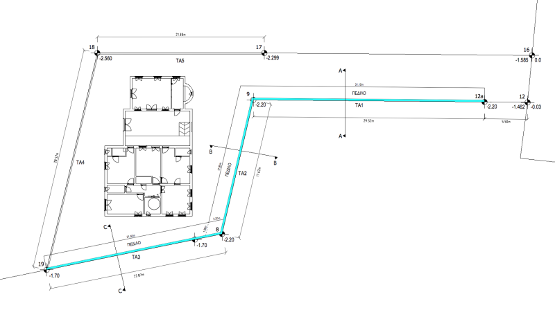
PLAN VIEW OF RETAINING WALL:

RETAINING WALL IS ILLUSTRATED WITH CYAN [highlight #729FCF]COLOUR[/highlight]

1st wall TA1 has a length of 30m
2nd wall TA2 has a length of 18m
3rd wall TA3 has a length of 23m

Screen_Shot_2018-03-31_at_14.06.09_yrmdn9.png


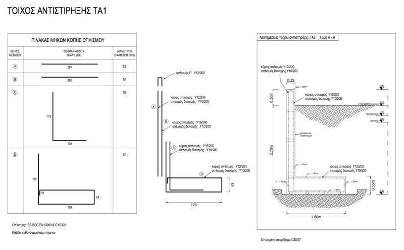
SECTION THROUGH WALL A-A

Screen_Shot_2018-03-31_at_14.06.48_h36snz.png
 
Replies continue below

Recommended for you

On NYSDOT projects expansion joints, including the footing, are spaced at 90’ max(although I have gone slightly over 100’ as a matter of practicality.) Control joints are spaced at 30’ but in the stem only. We don’t run the bars through the control joints.

 
bridgebuster said:
Control joints are spaced at 30’ but in the stem only. We don’t run the bars through the control joints.

Thanks for you reply, can you please elaborate on which type of control joint do you use?
1) sawcut or 2) v-groove?
 
Looking at your section view of the joint from above, I think you need to keep those horizontal bars back from the joint opening more, since cover is too small and bar corrosion can damage the joint.
 
If you want to bring the wall out flush with the footing, you should put a reglet at the junction of the wall and the footing.

Your dowel on the tension side can go to mid height of the wall to reduce your wall reinforcing and the footing extension can be shorter because it is in compression.

You also have to specify concrete cover to reinforcing.


Dik
 
See the attached drawing for joint details. I prefer a formed V-groove. I had a project where we saw cut joints but that was different situation. It was the rehabilitation of a gravity wall. We added a 5-inch overlay and cut the joints afterwards for aesthetic reasons.

On your wall I recommend expansion joints at Points 8 and 9, in addition to where ever else needed. At 8 you may want to think about an EJ each side of the intersection. I've inspected many walls and saw one with a corner similar to 8 that spilt the entire stem of the wall.
 
 http://files.engineering.com/getfile.aspx?folder=63a3c404-2cdf-457c-890a-1209be6bf8e1&file=005420_RetainingWalls_RFC_DQAE_Signed_040714.pdf
oldestguy said:
Looking at your section view of the joint from above, I think you need to keep those horizontal bars back from the joint opening more, since cover is too small and bar corrosion can damage the joint.

good advice however that is not my drawing, i just wanted to illustrate what i was talking about,
I have not yet decided if I am going to use an expansion/isolation joint


dik said:
If you want to bring the wall out flush with the footing, you should put a reglet at the junction of the wall and the footing. what is a reglet?

Your dowel on the tension side can go to mid height of the wall to reduce your wall reinforcing (my dowel on the tension side is actually 15cm above mid height, and i am thinking of reducing the reinforcement from 16mm bars to 14mm bars
and the footing extension can be shorter because it is in compression. you mean the width of the footing? actually the width of the footing is controlled by the sliding resistance of the wall, by increasing the width of the footing i am also increasing the walls resistance to sliding due to more weight acting on the footing

You also have to specify concrete cover to reinforcing. i have specified 5cm cover to reinforcement and C30/37 concrete

 
bridgebuster said:
See the attached drawing for joint details. I prefer a formed V-groove. I had a project where we saw cut joints but that was different situation. It was the rehabilitation of a gravity wall. We added a 5-inch overlay and cut the joints afterwards for aesthetic reasons.

Yes i too prefer a v-groove contraction joint, shall i also cut every other bar at each contraction joint?


On your wall I recommend expansion joints at Points 8 and 9, in addition to where ever else needed. At 8 you may want to think about an EJ each side of the intersection. I've inspected many walls and saw one with a corner similar to 8 that spilt the entire stem of the wall.

ok to be clear, when you say expansion joint you actually mean to divide the wall into a number of sections that will be poured independently, with discontinued horizontal reinforcement??

in order to better understand what you want me to do at corner 9 please answer the following question

shall i use this type of reinforcement at corner 9?

Screen_Shot_2018-04-01_at_01.21.20_wynurf.png
 
My biggest concern now is the footing, because we are pouring next week, therefore my question now is:
Do i need any expansion joints or contraction joints in the footing?
 
bridgebuster:

Do you have an actual product name for the waterstops you use?

Dik
 
Because the foundation is exposed at the face, you should have joints, else, you will have cracking on the front wall at the base. As noted, you should have a reglet at the base to wall joint to prevent 'ugly' concrete leaking.

You don't want a joint at the corner, but, a couple of feet on either side of the corner.

Dik
 
kellez said:
good advice however that is not my drawing, i just wanted to illustrate what i was talking about, I have not yet decided if I am going to use an expansion/isolation joint

Because the footing is exposed, you need to put a control joint in it to help it to crack at the location of the wall cracks... else, the crack will show up at a random location, possibly near, the wall joints.

I've attached a sketch of a reglet. When you cast concrete against a concrete surface, part of the liquid drips through the joint line, staining the surface of the existing concrete surface. A reglet helps avoid this, and gives a neater finish if exposed. You will have to revisit your vertical wall reinforcing.

You can caulk the reglet after all is cast and hardened...

Dik
 
 http://files.engineering.com/getfile.aspx?folder=2757454f-7be8-45de-aa80-dd05f2cd6ccd&file=Reglet.pdf
OP
Not the width of the footing, the length of the compression bar.... you only need a compression development length.

Dik
 
Therefore the conclusion is

1) Create contraction joints on the footing, located exactly where the contraction joints of the stem are.

The contraction joints on the footing should be vertical or horizontal?

Therefore no expansion joints are required on the footing?

Also there is no need to divide the footing in two or more different sections?


2) Use a reglet at the base of the wall to prevent 'ugly' concrete leaking.
 

dik,

This is a link to the NYSDOT approved list of PVC waterstops manufacturers:

Link

I've seen every other horizontal bar cut at the joint and no horizontal bars running through the joint.

yes. Yesterday, when I first read your post, I didn't notice wall lengths; two expansion joints should work
 
bridgebuster said:
yes. Yesterday, when I first read your post, I didn't notice wall lengths; two expansion joints should work


1) The expansion joint should also be formed within the footing as well?
do i need to divide the footing in different sections with discontinued reinforcement?


2) the first wall TA1, is 30m long, do you think one expansion joint in the middle is enough?
 
Create contraction joints on the footing, located exactly where the contraction joints of the stem are.

because the footing is exposed, joints should be made at the wall locations, else, you may have 'random' cracking is exposed concrete.

The contraction joints on the footing should be vertical or horizontal?

Joint should be vertical, in the face of the exposed footing.

Therefore no expansion joints are required on the footing?

No... if the cost is insignificant and appearance is necessary, you need joints.

Also there is no need to divide the footing in two or more different sections?

not longitudinally, but transversely.

You also need drainage behind the wall... I posted a reglet detail. This is often used at a horizontal joint to separate two or more concrete pours. When you cast the stem wall on the footing, cement paste will leak out of the joint and form a visually displeasing joint. The reglet helps prevent this. You might consider using a decorative form liner to provide something other than a plain concrete wall.

Dik
 
BB, thanks... I've already extracted the joint materials and details... you may want to check with the RT discussion...

Dik
 
OP - number 2 is what I do typically.
Also, in a typical footing that’s below grade no joint is needed but if your footing is above grade then extending the joint through footing is not a bad idea.
 
You may wonder why the third posting is gone. Perhaps they told you. My view is that since this is your first project with a job like this you are likely to miss something important. Since I saw major flaw in your posts, what will your insurance say as well as any contractor associated when the major failure happens with fresh concrete spilling all over the place?. Getting advice here is fine, but there is no way we can cover all the aspects. You really need the guidance there from a well experienced engineer if only for a review of what you have and then gives you a nod of approval. Think about what can go wrong, since THAT is very likely from what I see with your posts. The saying goes something like this: "Pride goeth before a fall". Substitute an applicable word for "pride". Self confidence maybe? Good luck!!!!
 
Status
Not open for further replies.

Part and Inventory Search

Sponsor