Continue to Site

Eng-Tips is the largest engineering community on the Internet

Intelligent Work Forums for Engineering Professionals

  • Congratulations KootK on being selected by the Eng-Tips community for having the most helpful posts in the forums last week. Way to Go!

Reinforcement charts in excel spreadsheet: Concrete columns 5

Status
Not open for further replies.

Pretty Girl

Structural
Nov 22, 2022
60
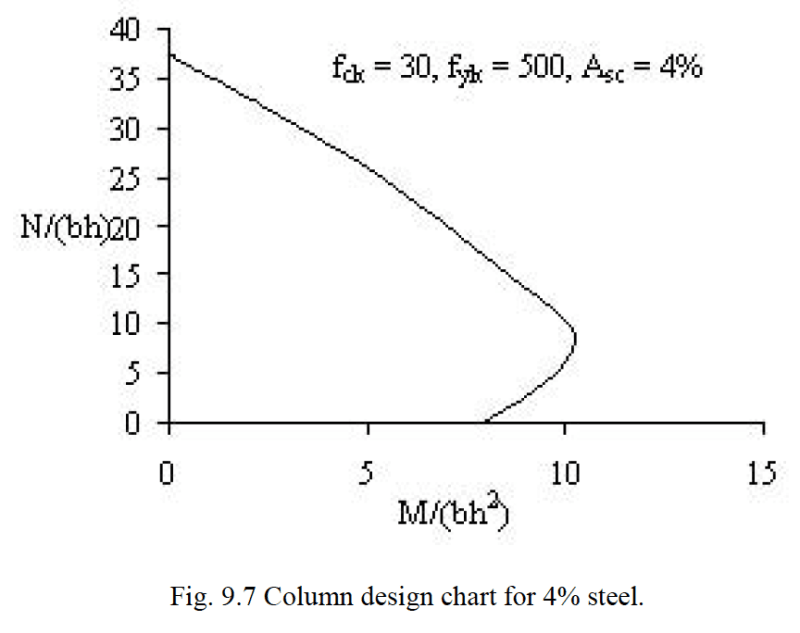
I tried to create an excel sheet to create new reinforcement charts for rectangular and circular concrete columns for Eurocode2.
I referred the calculation in the book "Reinforced concrete design to eurocodes by prab bhatt"- Page 355, section 9.2.5.1

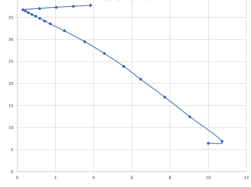
But after I get all the calculations in the spreadsheet, it doesn't look like the line in the following chart
Screenshot_2023-06-30_at_11.56.36_pm_zn4lnu.png


Is there any other books/videos etc which shows step by step calculations to produce charts? So, I can cross check and rectify my spreadsheet?
 
Replies continue below

Recommended for you

What does it look like?

-----*****-----
So strange to see the singularity approaching while the entire planet is rapidly turning into a hellscape. -John Coates

-Dik
 
I don't know of any specific thing that goes over it, but the best way to do this is to follow a textbook example for a column interaction diagram. Then you can verify each step. There's a lot of little things you need to watch out for, like not letting the steel stress go over the yield strength, and any little mistake will mess up the graph.
 
@JedClampett
No, it looks like this and I can't figure out why. I have many points though, did multiple calculations through excel.
666_y1r1lg.png
 
@milkshakelake
That's what this post is about, I'm trying to find some book etc which contains correct steps.
 
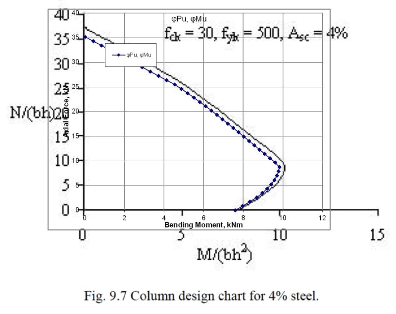
This is what I get using my RC Design Functions spreadsheet, based on a rectangular section with equal reinforcement in the top and bottom face:
EC2ColumnDesign2-1_kpskyk.jpg


The blue curve shows my results. The difference from the book graph may be due to my including the additional reduction factor in the UK National Annex, and/or different assumptions about the cross section or distribution of steel.

From your graph it looks like you are not taking moments about the composite section centroid, since you are getting an increasing bending moment as the stresses approach uniform stress across the section. If you can post your spreadsheet I'd be happy to have a look at it.

Another resource you might find useful is:
which generates bending/axial load capacity results for circular sections to Eurocode 2, including detailed calculation output.

I have also attached my spreadsheet with the interaction diagram as shown above, on the Interaction Diagram tab.

Doug Jenkins
Interactive Design Services
 
@IDS
Thank you. Aren't the equations hidden in your excel sheet? or can they be viewed, so I can learn what went wrong.
 
The equations are not hidden, but they use user defined functions in VBA. The code is all open source, but working through it is probably not the easiest way to find where your procedure is going wrong.

To generate a graph matching the one from the book using on-sheet formulas rather than VBA should be quite straightforward. I'd suggest using a rectangular stress block and rectangular section with steel in equal areas at top and bottom face only, to keep things simple, then:

1. Calculate the steel yield strain, and design concrete compressive stress and steel yield stress.
2. Calculate the neutral axis depth for the stress block to extend over the full depth.
3. Generate say 20 equal steps for the NA position from close to the top face to the position found in step 2.
4. For each position calculate the strain in the two steel layers, then the stress.
5. For steel in compression deduct the concrete stress.
6. Calculate the force in each steel layer, the concrete compression force, and the nett force on the section.
7. Take moments about the gross section centroid for the steel and concrete.
8. That gives you the axial force and moment for each NA position, then just divide by bh and bh^2 respectively.

That should give a line reasonably close to the one in the book.

Doug Jenkins
Interactive Design Services
 
Milkshakelake's spreadsheet reminds me that my point 7 is wrong. Take moments about the concrete centroid, not the composite centroid. So for a rectangular section take moments about the centre of the concrete section, regardless of the reinforcement arrangement.

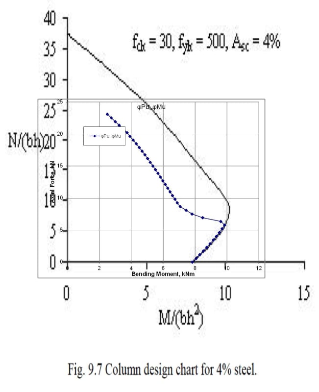
That is what my spreadsheet does, and using ACI as the design code it gives very similar results to milkshakelake's.

Note that the ACI code gives a very different shaped curve to Eurocode, which is because the materials reduction factors are applied as a single factor, with a much greater reduction for sections where compression controls, whereas the Eurocode has different factors for steel and concrete, so axial load capacity for very heavily reinforced sections is significantly higher.

ACI results for rectangular section with 4% reinforcement:
EC2ColumnDesign2-2_z7ezjd.jpg


Doug Jenkins
Interactive Design Services
 
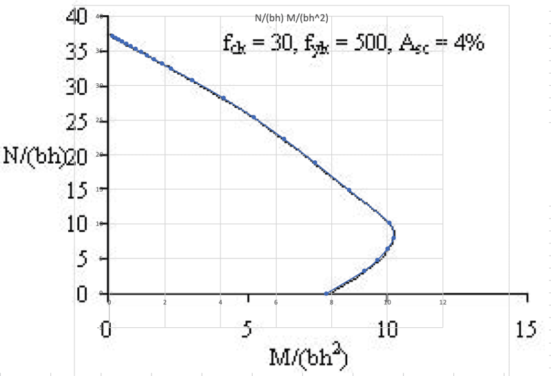
Thanks everyone, finally got it perfectly aligned with the chart

Screenshot_2023-07-07_at_8.31.01_pm_lhkma0.png
 
Hi Pretty Girl,

Could you please share here your spreadsheet?

Thanks
 
Hi,
Could you share the spreadsheet?


Thanks,

STRUKT
 
Status
Not open for further replies.

Part and Inventory Search

Sponsor