TylerM94
Structural
- Jun 2, 2020
- 26
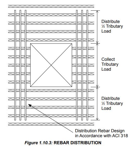
I recently came across a detail for a project a principal in my office is pier reviewing that calls for two #4 bars at all sides of an MEP opening in slab on deck. Rebar is to extend 3’ past the opening on all sides and max opening is 18” perpendicular to deck span.
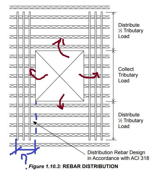
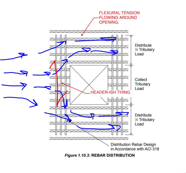
Can someone explain how this works structurally or how I would go about proving it? Is the idea that the rebar acts as a header in flexure and spans perpendicular? What if the contractor installs the rebar close to the top third of the slab?
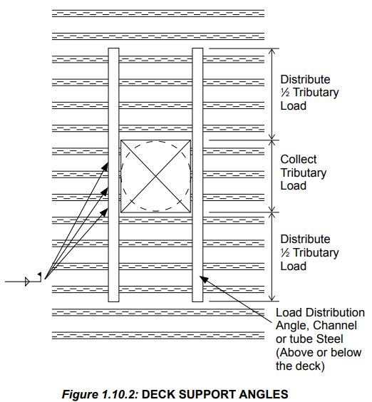
My office has a typical detail which allows an opening in slab on deck 2’ wide perpendicular to the deck span provided that a C5 channel is welded at each side of the opening spanning perpendicular to the deck. I haven’t run the numbers on it but conceptually it makes sense to me because you are heading off the load of the slab and using the channel to point redistribute the load to the ribs adjacent each side of the opening.
A conceptual explanation of the rebar approach would be much appreciated and if you would be able to describe the approach to proving this works structurally that would be appreciated!


