Continue to Site

Eng-Tips is the largest engineering community on the Internet

Intelligent Work Forums for Engineering Professionals

  • Congratulations KootK on being selected by the Eng-Tips community for having the most helpful posts in the forums last week. Way to Go!

reinforcing a four columns hydraulic press plates

Status
Not open for further replies.

sam_parts

Mechanical
Jul 8, 2019
5
hey guys,
first of all sry for my not well english :/
I have a question which has made my mind involved for a couple of days.

I've made a 80tons four columns hydraulic press recently that has 5cm iron plates as bolster and punch holder.
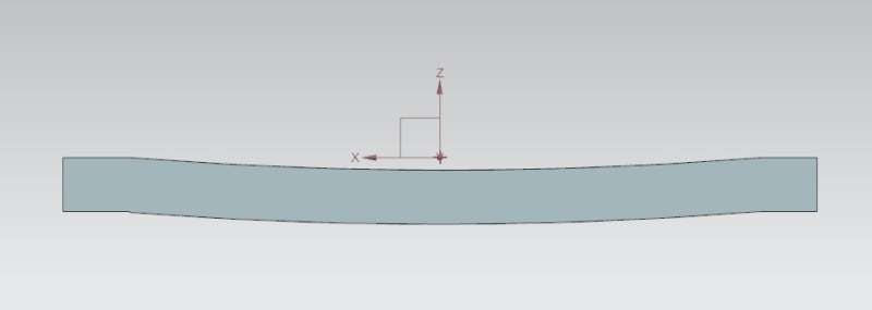
but as i expected (ooppss) the bolster and other plates are not strong enough for this tonnage and they bend under pressure.

now i want to reinforce these plates, the idea is adding some plates in their vertical side on the press plates (like the picture bellow).
but the problem is if I use bolts to attach these plates to the press plates they won't last long and all the pressure will be on the bolts and they may break.
and if i use welding the press plates will lose their accuracy and I want somehow do this without machining press plates again after welding.
unless you guys suggest another way to reinforce these plates.

Thanks in advance.
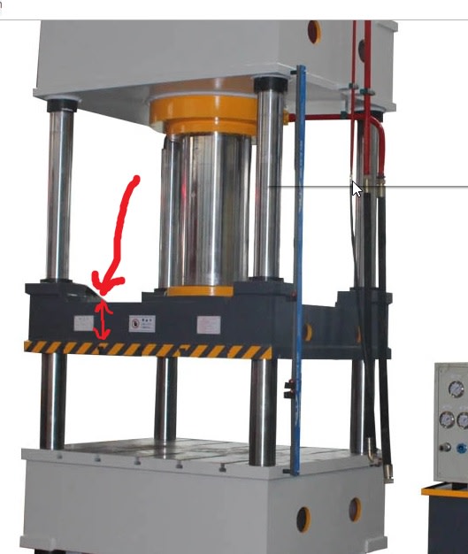
Untitled_cfah5k.jpg
 
Replies continue below

Recommended for you

Design the bolted arrangement so it will not break. If you weld, you will most likely have to machine the surface to make it flat.

Ted
 
How big is the object that you are pressing? Is the plate a solid piece? Seems to me like you're attempting to Band-aid the component in question; isn't it really an issue that the entire component is too wimpy for the job? Reinforcing the edges doesn't deal with the fact that the component is bending like a drum head directly under the ram. If the component is bending noticeably enough for you to worry about it, it seems to me that you would need to double(?) the effective thickness.

TTFN (ta ta for now)
I can do absolutely anything. I'm an expert! faq731-376 forum1529 Entire Forum list
 
Thanks for answers

@hydtools, Can u give me an example of bolted arrangement?
I'm trying to avoid machining it and reinforce keeping the surface flat, so welding is out of option i guess.

@IRstuff
700mm*700mm*50mm is the plates size of press,
I press multiple and difrrent objects, mostly sheet metal molds.
The press, cylinder, height, columns and etc are perfectly fine and strong enough for the job i just made a mistake
in the bolster and plates thickness. adding thickness is not the best and efficient way at the moment cause it needs double machining.

I was searching around and seems most of four columns presses like the one on the picture that ive posted are using not so thick plates but they are reinforced by the edges, or maybe the entire surface like meshing.

Anyway I'm looking for the best way to reinforce the plates.

Thanks a lot
seeking for new information
 
Perhaps the stiffening structure would look like a X corner to corner in a picture frame.

Ted
 
Can we assume that it looks the same in the y-direction> Because, if that's so, the reinforcing the edges will do nothing. You show it bending in the middle; how is that possible, is your die also bending? Something isn't thick enough or inherently stiff enough

TTFN (ta ta for now)
I can do absolutely anything. I'm an expert! faq731-376 forum1529 Entire Forum list
 
Sam_parts:
I would have to know a lot more about the entire system design; loads, die and punch shapes and structure, actual deflections on some grid on the plates, structural configuration of the platens (your plates), dimensions of the whole system, etc. etc. I would say there is a top platen, attached to the hydr. cylinder and there is a base pl. with the tee slots in it, and they both look too weak, not stiff enough. You are going to lose cylinder travel and you are going to lose head room under the top platen, unless you lengthen the four columns. To stiffen the top platen, I would fabricate a “cross shaped” structure which spanned in the x & y directions to apply loads on the edge webs of your current top platen, I don’t know what the interior of that platen looks like. This cross would have two vert. webs in each direction, spaced so the cylinder fit down btwn. them at the center. The bottom of the webs might be shaped to fit the interior of your platen, but would likely have to be shimmed, or flat spots on your platen provided, or some such, to apply loads in the right locations. I would likely put top and bot. flange pls. on these web plates to make the entire “cross shape” much stiffer and to pick up the cylinder loads at the center. This is all so dependent on what’s there that I really can’t go any further than that.
 
Status
Not open for further replies.

Part and Inventory Search

Sponsor