Continue to Site

Eng-Tips is the largest engineering community on the Internet

Intelligent Work Forums for Engineering Professionals

  • Congratulations KootK on being selected by the Eng-Tips community for having the most helpful posts in the forums last week. Way to Go!

Reinforcing Composite Open Web Trusses for RTU

Status
Not open for further replies.

CANeng11

Civil/Environmental
Feb 18, 2015
114
A client is placing a new RTU on two existing composite trusses. The trusses are in the style of the Redbuilt "Red-L" trusses, with wood top and bottom chords and steel webs. The building is from the 50's or 60's, so I believe the trusses were likely manufactured by Weyerhauser before they sold off this product to Redbuilt. Speaking with a rep from Redbuilt, these trusses were likely designed to be fully utilized, and adding any additional weight would overload them.

My question is whether reinforcing these trusses should be something we consider, or if we should add new support to take the RTU load separately from the existing structural elements? How would you reinforce this style of truss? Our initial thought was to stack an additional ply below the bottom chord, and add LVL's to either side of the top chord, but the connection may be an issue and this doesn't reinforce the webs, if that is required.
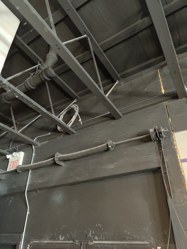
IMG_20201020_123504_kpcedp.jpg
 
Replies continue below

Recommended for you

What are those bracing members and how are they attached to the truss? I wonder if those aren't actually meant to be load distribution strong backs as I mentioned above. I still seek more inforation:

KootK said:
1) What's the span of the trusses?

2) Where about on the span will the unit go?

3) What's the spacing and depth of the trusses?

Give a little, get a little. Or maybe a lot, who knows.
 
Span of the truss is about 37 feet. They currently have the RTU positioned near midspan, but they are open to placing it near the end bearing at the steel beam side. The spacing is 32" o/c and the depth is 30"
 
Alright, so you've got trusses that should be capable of supporting at least 3,500 lbs total (1750 lbs end reaction). Adding 1000 lbs to 1750 lbs is a big deal so I like:

1) Midspan install to distribute shear increase (bending is easy to check) and;

2) Trying to share the load such that no one bearing seat is too overload.

If you engaged four trusses to support the load, you'd be down to about 125 lbs increase in the end reaction of each. 125 lbs / 1750 lbs = 7% increase. I could live with that and would prefer it to more invasive measures that often probably weaken a truss more than they strengthen it. Paper vs real world.
 
OP said:
Gotcha, so you are thinking creating a raft support for the RTU that spans over 4 trusses, similar to EdStainless's suggestion.

Correct. You can do the distribution above the trusses, below the trusses, or within the trusses. Above the trusses is probably easiest if that's feasible.

One thing that still bothers me is the load path out of the top chords and into the webs at the panel point joints. These joints are pretty awesome in that:

1) For transferring shear from one web to the next, that's done 100% via pins which load the chords not at all vertically.

2) The webs really only deliver horizontal shear to the chords and do so via kick-ass parallel to grain loading. I dig that.

What is not awesome is that any transverse loads applied to the top chords eventually have to make their way into the pins at the web joints through a bearing mechanism that I would think limited by some version of the dreaded, tension perpendicular to grain failure mode. That said, I've not yet seen how one of these joints looks up real close so I may be wrong about how they work. As a starting point, I'd grab a modern truss catalog and see what they have to say about concentrated loading there. That's probably based on testing which hasn't changed much over time.
 
I will look into applying a transverse point load on these trusses.

So to create the RTU support, would you just turn the unit so it fits between 3 joist spaces and span those 4 joists with something like 2-ply 2x6s on both sides of the unit, spanning between the 4 trusses?
 
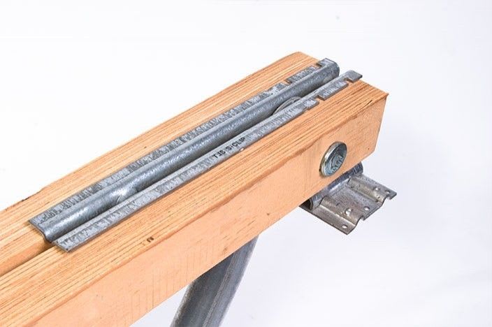
A little googling turned up this pic of a bearing seat joint. It's more robust than what I'd imagined. Do you see any evidence that your seat joint is something like this??

C01_xs35mu.jpg
 
OP said:
So to create the RTU support, would you just turn the unit so it fits between 3 joist spaces and span those 4 joists with something like 2-ply 2x6s on both sides of the unit, spanning between the 4 trusses?]

Kinda. Stiffness is your friend here, as is panel point loading. If possible, I'd throw some 18" LVL or 15" steel channels across the top chord panel points. Then infill between those with something to make a little bench of sorts.

The Steel Joist Institute has an extensive guide on joist reinforcement where they describe the distribution method in detail. That might be of use to you in sorting out the required stiffness.
 
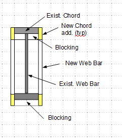
A suggestion for strengthening the joist. It minimize the interference with the pipe penetrations.

image_j07yx1.png
 
KootK said:
A little googling turned up this pic of a bearing seat joint. It's more robust than what I'd imagined. Do you see any evidence that your seat joint is something like this??

No, there's not much for a bearing seat at all.


So it looks like to determine whether the distribution beam is stiff enough, I would use the following equation:

β=∜((K∕S)∕(4EI))

Where,
K = The stiffness of the joist, kips/inch
S = The spacing of the joists
E = The modulus of elasticity for the beam
I = The moment of inertia of the beam

How would I go about determining the stiffness of these composite joists?

Also, how would you connect the LVL or C-Channel at the panel points of the joists?
 
OP said:
How would I go about determining the stiffness of these composite joists?

1) Do bending stiffness based on an estimate of the composite EI of the chords.

2) Add 15% flexibility to account for truss shear deformation.

OP said:
Also, how would you connect the LVL or C-Channel at the panel points of the joists?

Good question. Probably plop 'er down and try to connect things together with whatever screw & hardware bits your contractor prefers. It looks as though you've got a strapped roof deck so you'll need to factor that in. You might dump your load between panel points as needed and then run some kind of external web down from those locations to the bottom chord panel points as we do with OWSJ.


The additional chord members are analog to KootK's channels, both can be fastened to the existing chords through combination of wood adhesive, screws, thread roods and blockings. My concept is to put jacket (similar to sister) over the existing joist, that ends in much stronger joist. The pattern of the additions should match the existing, so the stiffness, and member stress can be easily calculated. General idea - the addition chords should be deeper than the existing to allow for free passing of rod (below the existing chord), and to provide blocking on sides of the rod (in between the additions) for tightening. Wood adhesive and screw/nail will be used to stabilize the additional chord members to the existing chords. By carefully select locations of splices, field installation is simple, and the result should be satisfactory.
 
One issue with your earlier weight increase calculation KootK, is the dead weight of these distribution beams. A 15" C-channel will be about 34 plf per side and a 2 ply 18" LVL will be 18 plf per side. With 8 foot beams, you would be adding 161 lb (9% increase) to each bearing point and with the c-channels 193 lb (11% increase. I think the c-channel could work over 5 trusses, but that would still add 172 lb to each bearing point.
 
Well yeah, the detailed run down is still very much up to you. I was just back of enveloping it, trying to help. Most reinforcement schemes wind up adding dead load.
 
Status
Not open for further replies.

Part and Inventory Search

Sponsor