Eng-Tips is the largest engineering community on the Internet

Intelligent Work Forums for Engineering Professionals

  • Congratulations waross on being selected by the Tek-Tips community for having the most helpful posts in the forums last week. Way to Go!

Relationship between pump discharge piping length and pump flow

Status
Not open for further replies.

NovaStark

Mechanical
Feb 11, 2013
238
1
0
US
Good day all,

I am trying to find any information I can on how the length of piping of a pump's discharge affects its performance/operation.

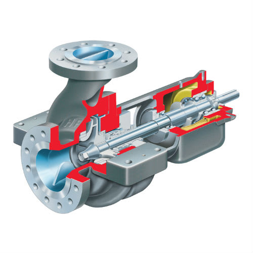
Consider a single stage OH type pump which takes atmospheric hydraulic oil and pumps it to a compressor at 180 psi. Suction enters the pump horizontally and discharges vertically.

If the distance between the discharge nozzle and outlet piping valve is 2 feet, how would this affect the performance/operation of the pump if the distance is reduced to 1 ft or even 6 inches ?

The main reasoning would be to remove as much air pockets as possible in the piping which is currently affecting the pump's performance.
 
Replies continue below

Recommended for you

The amount of time for start-up is insignificant, what is it - 20 seconds at worst.

What is the by-pass for anyway, normally only used to safeguard against operating against a "shut-head" condition or possibly by-passing excess product on oversized installation.


It is a capital mistake to theorise before one has data. Insensibly one begins to twist facts to suit theories, instead of theories to suit facts. (Sherlock Holmes - A Scandal in Bohemia.)
 
Is the delay in getting flow from the stand-by pump into the system a function of flow thru' the bypass line until enough head is developed to overcome the closed check valve?
Worth checking, the reason I'm saying isolate the bypass to prove it or otherwise?

It is a capital mistake to theorise before one has data. Insensibly one begins to twist facts to suit theories, instead of theories to suit facts. (Sherlock Holmes - A Scandal in Bohemia.)
 
Hmmmm.

Puzzling.

My only offer is that if the suction lines of the twp pumps are connected (i.e. only line of ?? size) and at a distance of ??ft from the reservoir, then the pressure at the pump inlet is several feet below atmospheric pressure. Hence the discharge piping, the bypass line and possibly part of the pump itself is drained of fluid by air coming back down the bypass line.

Hence when the pump starts the pump is trying to fill the pump casing, discharge line ( ?? diameter?) and the 1/2" bypass line before it really gets going.

Another thing to determine is how are these motors configured to start? DOL or some sort of soft start / variable speed start?

The other odd thing is this 1/2" line - your pump data sheet indicated a desired flow of around 300 to 400 USGPM - about 90 m3/hr.

I really can't see what a 1/2" line with a 4mm orifice is going to do for you. I can't be bothered to work out the flow at 180 psi, but I know it won't be very high, certainly not 10-15% of your pump flow.

The other thing is to figure out if pump A does the same?

An option might be to have separate individual suction lines from reservoir to tank?

If you could sketch out the entire system from tank through pumps and provide pipe sizes, lengths and flowrates we might get somewhere. And also figure out what the motor starter is.


Remember - More details = better answers
Also: If you get a response it's polite to respond to it.
 
@Artsi:

The time is usually between 20-25 seconds to go from 0 psig to 180 psig. The 4 seconds I mentioned is usually how long it take for the header pressure to drop below the trip limit that causes the machines to trip.

The bypass line is 0.5 inch with a 4 mm orifice in it, so the flow not being sent through the discharge might be minimal. So the issue is building the pressure within the 4 seconds or so.

We are still awaiting word from the OEM as to the recirc line's actual purpose, but we are assuming that it is to protect against the dead head type condition (as this is how most of our pumps are design). It could be as you said to bypass the excess product.
 
@LI:

I attached a piece of the P&ID for the system so it would be clearer.


Both pumps take separate suctions from the reservoir via a 6 NPS pipe at a distance of about 10 ft. away (estimated).

From the P&ID, 245 gpm (at 20 psig PCV controlled) goes to the lube oil for the machines and 36 gpm (at 165-190 psi)goes to control oil.

Pump A is driven by a steam turbine, so it doesn't automatically start but goes through the normal start up of warm up, to min governor and then to rated.

The motor on pump B is set to autostart if the header pressure falls below 165 psig or if the steam turbine speed falls by 100 rpm.

Yes, I think the flow through the 0.5 NPS line would be too small to be counted. But the 300-400 gpm did look like an anomaly.

 
 https://files.engineering.com/getfile.aspx?folder=d57fb0f9-4b64-420a-9c2f-a84851ea9049&file=PID.png
OK,

So what does PI 33-201-0202 measure during operation? (suction on the side of the tank)?

Does pump B have two orifice plates open (33-220 and 33-225

Have you checked that the orifice plate is actually there? and the hole is 4mm?

Wheres the oil return line? - Is that the CR3 nozzle?


If the baffle is clogged you could easily draw down the oil level in that half of the reservoir which would equalise slowly when no flow.

But my guess at the moment is still the motor starter.

Remember - More details = better answers
Also: If you get a response it's polite to respond to it.
 
@LI:

The two PIs measure suction pressure and is located outside of the tank.

Both pumps have the orifices however I don't believe they were measured.

Correct, the oil return is CR3.

That is a good point, the tank internals have never been cleaned since installed in 2008 or so. Could it be so dirty that the level of oil on both sides of the baffle is more than 10 inches ?
 
My point on the PI's is what are the readings?

10 inches is possible worth a clogged baffle.

12 years is a long time for things to block up or corrode.

Time for a good clean I think.

Any idea about the motor starter?

Remember - More details = better answers
Also: If you get a response it's polite to respond to it.
 
@LI:

The PIs are currently reading around 2 psig.

We tested the motor starter by simulating the low speed or LO pressure. It does auto-start and reach the rated speed within 2-3 seconds.

We did open the tank and note that the recirc lines do extend into the oil however there are are two 1/4" holes drilled into each line just below the top of the tank.
 
Is flowrate known?
What is pump speed?
The duty point on the supplied curve is 309 USgpm @ 566 ft, this is way over the 180psi you are reporting.
Time to sit down and correlate all your data and advise, currently going round and round in circles with the actual pump / installation performance unknown.


It is a capital mistake to theorise before one has data. Insensibly one begins to twist facts to suit theories, instead of theories to suit facts. (Sherlock Holmes - A Scandal in Bohemia.)
 
This is a puzzle alright.

You will need to try and do a few diagnostic runs to gather data on the start up.

Get all your levels and distances worked out. (Liquid level, pump centre line, bypass line elevation etc

So monitoring the fluid pressures and temperature is one
Can you also monitor motor voltage and ampage.
Initially it will be high as it starts, but its what it does from 3 seconds up to the 20 seconds when it finally gets on line which will be important. Then you can have some idea of whether the flow through the pump is low ( relatively low amps) or off the end of the curve( high amps). The breaker might not trip as the motor starter will inhibit this for a certain time frame.

That hole will allow the discharge piping to slowly drain back through the pump. The issue for me is how far back it drains.

what SG are you running at?
Does the 2psig equate to the correct level in the tank?
Can you observe the level in the tank during operation on both sides of the screen?

Remember - More details = better answers
Also: If you get a response it's polite to respond to it.
 
@Artsi:

Flow rate is unknown
Pump B operates at 3550 rpm
Pump A operates at 3650 rpm

I do agree that is an unknown, but there are several other orifices installed in the system before oil goes to the lube oil and control oil system. So there may be some pressure switches that continuously drain back to the reservoir. I will try to post the entire P&ID if I am able to.

@ LI:

I will try to measure these elevations as best I can.

Not sure about if the Volt/Amperage can be continuously monitored or if point readings can be recorded.

Draining back through the discharge seems to be going on but it seems to be doing it all the way to below the recirc line. I did also check API 614 which doesn't show a hole being required in pressurized return lines so I am not sure if was an error in initial fabrication.

SG = 0.856
I'll recheck the suction PI reading and try to correlate with the tank level as best as I can. Unfortunately, the baffle blocks a good view of the oil on the suction side.


@shashankTurbomachine:

The 15d on the discharge nozzle to the check valve does not appear to be 15d


Also, we have started up the machines using Pump B only on previous occasions. So I think the flow out of the pump may not be a big issue (unless I am overlooking something here).
 
Your 180 psi off your pump data sheet, assuming that the inlet pressure is virtually atmospheric, gives me 470 ft. at that head differential you're at nearly 500 GPM, right at the end of the curve. So not the 300 your P&ID quotes.

It think you might be starting this thing way right of the curve and it's chewing itself up with NPSH issues.

I think this could be a system issue depending on how the oil is used. If some system detects low oil pressure and opens up the controller to increase flow then as the pump starts it doesn't have enough back pressure and just pumps into a system which takes time for the pressure to build and drag the pump back onto its curve.

Maybe.


Remember - More details = better answers
Also: If you get a response it's polite to respond to it.
 
NovaStark: without flowrate you have no idea where the pump is operating or trying to operate within its performance capabilities. Currently all that is know is - something is not right! the number of orifices, valve, pipes, drains are meaningless without understanding what the pump is actually doing.

It is a capital mistake to theorise before one has data. Insensibly one begins to twist facts to suit theories, instead of theories to suit facts. (Sherlock Holmes - A Scandal in Bohemia.)
 
@LI/Artsi:

With the discharge fully closed, the shutoff head should ideally be immediately reached correct?

While we don't know exactly where the pump operates, we did try shutting the discharge valve, then starting the pump and while it was slowly building pressure, the discharge was slowly opened which saw the pressure immediately build.


I'll try to get more information (as much as I can), but without assuming that the pump curve is incorrect, it's all we have to go on for now.
 
That's beginning to look like the pump casing isn't full at the start point or has some air trapped in it somewhere. whats the orientation of the discharge nozzle on the pump? (Any pictures?)

At discharge valve closed then yes, you should get to shut in head pretty fast (<5 seconds)


Remember - More details = better answers
Also: If you get a response it's polite to respond to it.
 
LI / NS.
LI, your second last post and mine, both stamped at the same time must have just about collided with each other on arrival, both saying virtually the same - the pump is trying to operate well out of its hydraulic range or way off the end of curve, as for cavitation (oil) a bit outside my expertise and more inline with your area, but seems the problem is likely hydraulic.

NS. the pumps are steam turbine driven, correct?
Are they or can they be speed regulated?
At the moment it appears the pumps could be way oversized, can they be speed reduced to get pump output back to somewhere near the "design" duty?

It is a capital mistake to theorise before one has data. Insensibly one begins to twist facts to suit theories, instead of theories to suit facts. (Sherlock Holmes - A Scandal in Bohemia.)
 
@LI:


The suction is horizontal and the discharge is vertical as shown below:
Flowserve-Flowserve-APIProcessPumps-HPX_fspyjl.jpg


@Artsi:

Pump A is steam turbine driven (for some reason it is operated around 3650 rpm) and Pump B is motor driven (3550 rpm). So only the steam turbine can be manipulated.

I have attached the full P&ID to give you all a good idea of the unit (removed any identifying markers).
 
I think an area to consider is the potential some how for air to get into the top of the pump casing which then takes time to flush out with flow. see the section below. It might be top exit, but the opening is about halfway up the pump.

pump_section_f2kfkl.png


You are probably getting some flow going back through the loop which slowly fills the pump and that's when the pressure rises. in normal operation you won't be getting forward flow until the pump discharge pressure is greater than the system pressure. Then you start to get flow then the sir clears out and the pump recovers back to normal operation.

Now how you're getting air in there is an issue, but I think it needs to be investigated and see if you can change this somehow.

If the suction is under positive pressure then you should be able to vent or auto vent prior to start.

The hole in the pipe btw will be there to prevent syphoning of the liquid.

You P&ID looks ok, but there is something not right with the flow vs pressure. If the discharge pressure is actually 180 psig, then you appear to be pumping a lot more than 300 GPM. But I don't think that is directly related.

I might easily be wrong about the trapped air, but see if this works. Is there a vent plug on the top of the pump casing? Can you attach a valve and see if you have fluid coming out whilst pump A is working or not?. If you do my theory is wrong, but if you don't then it might be right.

Remember - More details = better answers
Also: If you get a response it's polite to respond to it.
 
LI, you have shown a side discharge pump casing, the pump in question is a top centreline discharge which are virtually self venting, one of the main advantages of this style, although air trapped by a check or gate valve is still a problem and can airlock the case.

It is a capital mistake to theorise before one has data. Insensibly one begins to twist facts to suit theories, instead of theories to suit facts. (Sherlock Holmes - A Scandal in Bohemia.)
 
Status
Not open for further replies.
Back
Top