Continue to Site

Eng-Tips is the largest engineering community on the Internet

Intelligent Work Forums for Engineering Professionals

  • Congratulations KootK on being selected by the Eng-Tips community for having the most helpful posts in the forums last week. Way to Go!

Relay Coil Suppression with single Zener Diode across BJT 4

Status
Not open for further replies.

JDW0

Automotive
Mar 22, 2016
15
In terms of relay coil voltage spike suppression, the following thread focuses on using a 1N4007 diode in series with a Zener across the relay coil:

thread248-291225

But there are times when you need to suppress coil spikes but cannot put components across the relay coil. In this case, a single Zener diode across the Collector and Emitter of a common-emitter BJT (which drives the low side of the relay coil), should be adequate to suppress the coil's voltage spike to the Zener voltage. And using a Vz = 2 x Vcc (with Vcc being the coil's positive voltage) would ensure the presence of the Zener does not slow the switching mechanism in any significant way.

My question is how to properly calculate the wattage / power rating of the Zener. While we could just use a multi-Watt Zener "for safety," that is a rather "shot-in-the-dark" method that ignores size and cost. A 0.5W 1N5252B 24V Zener costs much less than a 5W 1N5359B 24V Zener, and there is a large size difference as well. As such, it is advantageous to know if the smaller and lower cost 0.5W Zener would be a long-term reliable choice to suppress relay coil spikes.

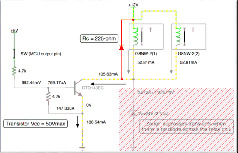
Consider this circuit:

Image%202017-06-13%20at%201.52.33%20PM.png


The OMRON G8NW-2 relay shown is a single device that houses 2 coils and 2 switches. Here is the datasheet:

In the above circuit we are using an NPN BJT to switch the low side of both coils, with their high side connected together at an automotive +12V. (That 12V is filtered, so don't mind about Load Dumps.) The Zener voltage was chosen to be twice Vcc, which is 24V. The resistance of one relay coil is 225Ω at 20°C, but the datasheet shows a worst case of 180Ω at -40°C. Low resistance means more current flow. At 225Ω we have 0.64W and 53mA current, but at 180Ω we have 0.8W and 64mA current; and again, that is for only 1 of the 2 coils.

I built a test circuit that matches follows the above schematic, first without any suppression and then with the Zener across the collector and emitter. On a scope I measured relay coil spikes at the low side of the relay coil (at the Collector of the BJT) to be from 100V up to about 143V:

Image%202017-06-13%20at%203.48.29%20PM.png


The transistor used has a Vcc=50Vmax specification. Vce (voltage across the Collector and Emitter) will obviously be lower than Vcc with the relay in the circuit, low side connected to the Collector. But even if Vce was spec'd at 50V, that's still only half of the measured voltage spikes coming off the relay coils. As such, we need to protect the transistor, and that's where our Zener across the Collector and Emitter comes in.

Assuming a safe maximum Vce of 40V, it takes between 150us and 175us for the spike to decay to that level (varies by Vcc voltage level):

Image%202017-06-13%20at%203.50.44%20PM.png


Image%202017-06-13%20at%203.51.46%20PM.png


And with the 0.5W 24V Zener connected across the transistor, we see this on the scope:

Image%202017-06-13%20at%203.53.08%20PM.png


Image%202017-06-13%20at%203.53.37%20PM.png


But what is the minimum reliable wattage rating we should choose for the 24V Zener? That's my question. These are short-term voltage spikes, not continuous high voltage. And again, there are times when you need to reduce both cost and size, making a random selection of a high-wattage Zener impractical. I used a 1N5252B 24V 0.5W Zener across the transistor with the OMRON relay shown in the schematic for my measurements above. I've even used that same 0.5W Zener in a bench-top test circuit with 2 larger automotive relays which draw 122mA each. I only tested for a matter of minutes, not hours or days or weeks. But the 0.5W 1N5252B did not blow. (And actually, even without any suppression at all, for my short-term bench testing, the high voltage did not fry the transistor.) So I am curious if a 0.5W rated 24V Zener across the transistor would be a long-term reliable choice for relay coil spike suppression in this particular application.

I would appreciate hearing your thoughts.
 
Replies continue below

Recommended for you

Best way to tell is to put a low value resistor in series with Mr. Zener and then scope the voltage across the resistor during a transient which will give you the current pulse thru the zener. Then don't go to any clapped-out crap data sheets like the defective ones ON Sloppyconductor company has screwed up from the good Fairchild data sheets but instead go to someplace like Vishay and look up the zener. In their data sheet they will have a graph that shows the maximum current at the zener voltage. See where your current spikes land on that graph.

Keith Cress
kcress -
 
Howdy JDWO,
Why not simply put a free-wheeling diode across the relay coil(s)? This is done all of the time. You can even buy (some) Omron relays with the FWD already built-in.
GG

Drawing1_mvyby1.gif


"I have not failed. I've just found 10,000 ways that won't work." Thomas Alva Edison (1847-1931)
 
Groovy guy, the straight diode works, but can cause very slow dropout of the relay, and possibly bounce of the contacts, which can degrade contacts due to repetitive arcing.
 
What about high speed TVS diodes?

-AK2DM

~~~~~~~~~~~~~~~~~~~~~~~~~~~~~~~~~~
"It's the questions that drive us"
~~~~~~~~~~~~~~~~~~~~~~~~~~~~~~~~~~

 
analogkid2digitalman, a TVS diodes would be more expensive than a single Zener, and as mentioned in my opening post, the aim here is good long-term suppression at the lowest possible cost.

GroovyGuy, btrueblood already posted an answer for you, but I wish to further answer it by repeating what I said in my opening post. Some circuits are designed to have a BJT output that is used to drive an external relay. You don't know if that relay is suppressed and in most cases it is not. That means in that kind of circuit, it is IMPOSSIBLE to put any suppression "across the relay coil" and expecting people to do that external to the circuit, on the relay itself, is not something we ought to assume. Therefore, my circuit is sound in that the suppression component is placed across the Collector and Emitter of the BJT transistor. The benefit of the Zener is that it doesn't slow down the relay operation like a simple diode across the coil. A diode across the coil may result in tack-welding of the relay contacts, but a Zener across the BJT would not. So why even start this thread? To determine the best "wattage rating" for the Zener, keeping cost concerns paramount.

itsmoked, I followed your advice as follows...

I used my Fluke 8845A to measure the exact value of a 10Ω, 5%, 0.5W resistor, after 1 hour of warm-up, and the 2x4W probe, with 6-digit, 100PLC precision. After settling time, the reading was 9.8651Ω. The rightmost digit was fluctuating a bit, but it's safe to say the resistor is 9.865Ω at room temperature, the temperature at which I conducted the scope test.

I put that 9.865Ω resistor ("Rtest") in series with my 24V 0.5W Zener as shown in this schematic:

Image%202017-06-14%20at%2010.20.32%20AM.png


I used both scope probes, putting them on either side of the resistor. I then toggled the relay with my MCU. I tested repeatedly. The maximum voltage I could measure on the scope, on the relay side of Rtest was 26.0V (CH2):

Image%202017-06-14%20at%2010.38.22%20AM.png


At that CH2=26.0V, the other probe (CH1) consistently measured 25.2V. So the voltage drop across Rtest is:

26.0V - 25.2V = 0.8V

Therefore:

i ("current pulse") = e/r = 0.8V/9.865 = 81.1mA

The Vishay datasheet for the 1N5252 (24V, 0.5W) Zener is here:


Note Fig. 9 at the top right of page 4, which shows Iz vs Vz. It's below 20mA for the 24V Zener, and none of the Zeners shown are above 30mA. So the datasheet gives the 1N5252 a thumbs down for relay coil spike suppression. Even so, in my repeated testing, the 1N5252 does not blow. Why not? Because the spike duration is very short. When the 24V Zener suppression is used, my scope measurements show that the total time the spike is surpassed, including decay time, is almost exactly 2.0ms. Ignoring the slow decay (which is at 26V or lower, safe for the BJT), the actual spike suppression time is more on the order of 900us (and the highest voltage part of the spike has a duration of about 150us (142V to 40V, shown in the first scope photo in my opening post).

Now consider that relay activation is performed by an MCU. There's a push button switch that allows the user to energize or de-energize the relay. And there is a timer for switch debouncing that prevents the user from energizing the relay more than once every couple seconds. In other words, even if one energized the relay as often as possible, the OFF time (no spikes) is measured in seconds whereas the ON time (triggering spikes) is 900us. That ensures the Zener is not being heated.

Despite all this, I am really at the same place at which I originally started this thread. The 0.5W 24V Zener across the BJT works in practical bench testing and logically I see why it is not blowing. But I am simply curious about long term reliability (several years of use).

When checking the datasheets of 1W rated 24V Zeners (which are twice the price of the 0.5W 24V Zeners), even the glorious datasheets of Vishay, there is no Iz vs. Vz graphs at all. However, many datasheets for the 1W Zeners have a "Non-repetitive Peak Reverse Current" or "Maximum Surge Current" column in their specifications tables. The 1N4749A is a 1W 24V Zener that can withstand 190mA for 8ms, which would seem perfectly adequate for coil spike suppression.

I would appreciate hearing your thoughts.
 
"The 0.5W 24V Zener across the BJT works in practical bench testing and logically I see why it is not blowing. But I am simply curious about long term reliability (several years of use)."

It will likely die. Repeated overstressing is one common method for running accelerated life tests.

TTFN (ta ta for now)
I can do absolutely anything. I'm an expert! faq731-376 forum1529 Entire Forum list
 
Use a TVS diode (Transient Voltage Suppression) like a Little Fuse 1.5KE series.
 
A LittleFuse 1.5KE27A 27V TVS diode costs 6x more than a 1N4749A 1W 24V Zener at in quantities ranging from 1000pcs to 20,000pcs. It makes absolutely no sense to use a part costing 600% more when the suppression result and protection of the BJT and relay is the same. And while a 1N4007 across the relay coil is cheaper still, it potentially harms the relay AND you are forced to use it across the coil.

As mentioned in this thread, there are times when you need to provide an open collector output that will be used with a an external relay concerning which you do not know if external suppression is used. That's why a 24V Zener diode across the transistor is really the best suppression choice, because you then need not worry about a suppressor across the coil. It would also appear that a 0.5W 24V would not be up to the task in long term use, hence the decision to go with a moderately more expensive 1W 24V Zener instead.
 
When I read this thread, I couldn't help but think it would be an interesting exercise for a Spice simulation.

Please Note: I am wayyy out of my discipline in electronics, it's just a hobby for me, and I have used Spice (LTSpice from Linear Technologies) for a total of 5 hours. This is worth what you pay for it.
I'm doing this as much for my own education as for the possiiblity that it might help you.

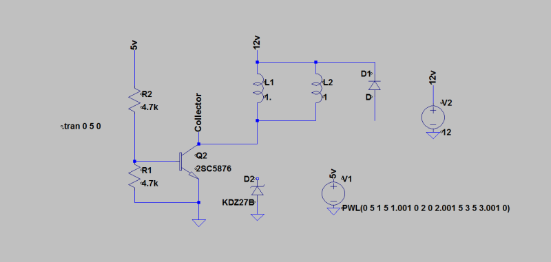
Here's the circuit I drew:

Relay_Control_Circuit_Suppression_methods_shtvn9.png


I selected the components from the list of available elements in LTSpice, NOT the components JDW0 is using - those simply aren't available without manual configuration of the individual element properties.
That said, I tried to select components relatively close:
Transistor 2SC5876 has a Vceo of 60V and collector current of 500mA
The Zener diode is a Rohm TDZ24B whose breakdown voltage is 24V
The plain diode is a 1N4148 - but doesn't seem to matter what I pick
There are no relays, as far as I can see, in LTSpice (I must be missing something) so I placed an inductor coil with approximately the right properties.
For the inductance of the coils, I measured the 28VDC coil of a relay I happened to have on my desk. It was 2.6 Henrys, so I assume a 1.0 Henry inductance on the 12V coil in the model.
I will comment on the coil resistance below...
To measure the voltage spikes, I created a Node called Collector which I attached to the collector of the transistor.
This node is plotted on the graphs that follow.

The circuit as you see it is in "no suppression" mode. The plain diode across the coil is not connected, and the zener is not connected either.
Spice can run the simulation with these disconnected components and they have no effect.
To engage either suppression method, I just have to draw the wire that connects the component.

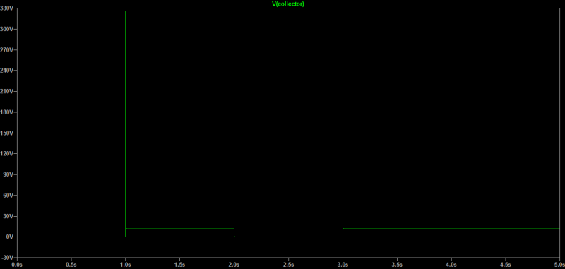
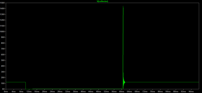
Here's the voltage plot at the Collector with NO suppression:

Relay_Coil_Spikes_no_Suppression_fgy43r.png


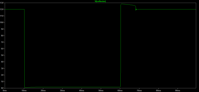
Here's the voltage plot at the Collector with Diode suppression across the relay terminals:

Relay_Coil_Spikes_Diode_Suppression_u7nz1u.png


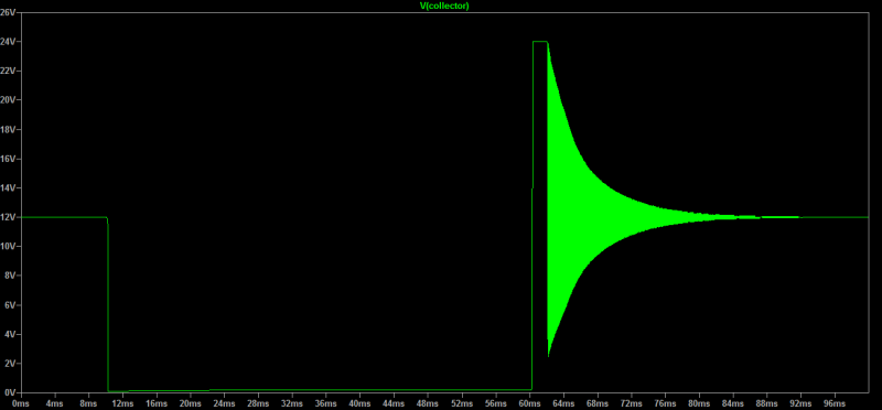
Here's the voltage plot at the Collector with Zener suppression across the transistor:

Relay_Coil_Spikes_Zener_Suppression_aec34w.png


Footnote: When I set the resistance of coils 1+2 both to 225 Ohm the simulation gave me a huge hash that I assume is resonance or ringing on the Collector that never damped out. When the value of coil 1 or 2 was set to a slightly different value the ringing disappeared quickly. The plots above are at 225/220 ohms, respectively, and have no more ringing.

Hope this is helpful or interesting!

Attached below is a copy of the circuit file.

STF
 
Sorry, forgot to mention, I controlled switching of the transistor by supplying a pulsed 5V source.
The 5V source is ON for 1 second, OFF for 1 second, ON for 1 second, then OFF and stays off.
The rise/fall time on each pulse is 1 msec.


STF
 
Hi SparWeb,
It is interesting that your model seems to indicate that the free-wheeling diode (FWD) is the most effective at suppressing the voltage peak. I was also surprised to see the peak voltage of > 300V when no suppression is provided. Perhaps I shouldn't be surprised though, knowing the impact that di/dT can generate when dT->0.
I have always used FWDs on (thousands of) DC relay coils, and MOVs or snubbers on all AC coils, so far have not blown any output transistors.
Thanx for your input.
GG


"I have not failed. I've just found 10,000 ways that won't work." Thomas Alva Edison (1847-1931)

 
One would have thought that an FWD's lower forward voltage and, therefore, lower, required power rating, would have a big advantage. When you compare running even a 1V forward drop vs. a 24V Zener breakdown, that's got to be a significant advantage.

TTFN (ta ta for now)
I can do absolutely anything. I'm an expert! faq731-376 forum1529 Entire Forum list
 
My 2 (maybe 3) cents:

I hooked up two 12 V relay coils in parallel and tested with different combinations of 1N4118 (no zeners) and resistors in series with it.

The recordings have been augmented with comments. First - no series resistor:

12_V_relay_and_1N4118_timing_on_off_1_w_comments_cropped_jrgsc1.png


The kick-back voltage is, as expected, very low (one diode drop) and the off delay is 12.6 ms. There is bounce.

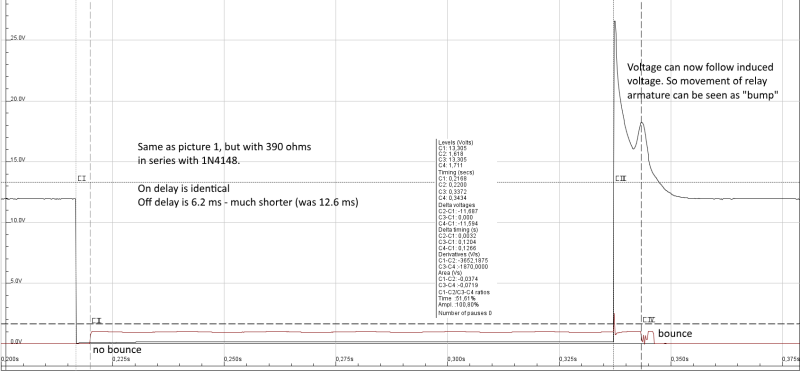
Next is with the 390 ohms resistor:

12_V_relay_and_1N4118_plus_390_ohms_timing_on_off_1_w_comments_n9on7y.png


Kick-back is ariund 25 V, also expected, and off delay is now shorter with 6.2 ms. Not much influence on bounce.

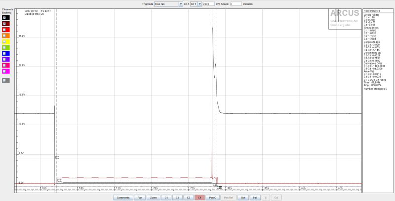
I also ran a test with 2x390 ohms. The delay is somewhat reduced and the kick-back is higher. So high that the measurement range was exceeded. So no further comments on that one.

12_V_relay_and_1N4118_plus_2x390_ohms_timing_on_off_1_izoter.png


Gunnar Englund
--------------------------------------
Half full - Half empty? I don't mind. It's what in it that counts.
 
Hi Gunnar,
It's interesting to compare our results. Can you measure the inductance of the coil on your relay?
My measurement of 2.6 Henrys (on the relay I have on my desk) makes me doubt my multimeter... It seems too high.

Inductance of the coil was the strongest determinant of the spike voltage (perhaps obvious, to some) so I'd like to have a better "gut feel" for realistic values.

Relay datasheets don't typically publish a value for coil inductance.
And good luck trying to google-search the subject because all you get is the contact rating when switching "inductive" loads... :

STF
 
"seductive"? perhaps?
will measure later - midnight here

Gunnar Englund
--------------------------------------
Half full - Half empty? I don't mind. It's what in it that counts.
 
SparWeb, thank you for the SPICE simulation.

GroovyGuy (and everyone else), although the 300V may appear on the simulation, the actual benchtop circuit measurements I provided earlier in this thread were the peak voltages detected on a scope in my testing over the course of 1 hour. In other words, I saw only half that 300V. But there are variances that a simulation cannot account for, hence my measured values being lower.

As to a cheap diode across the relay coil, there are zero surprises about it's effectiveness in "spike suppression. In fact, in my benchtop circuit test with a scope, I don't even see that little blip of a spike on the left side of the pulses shown in the spike simulation. Hands down, if you need to suppress relay coil kickback, a cheap diode (1N4007) across the coil will do it. BUT, and this is a big BUT and the very foundation of this thread, a cheap diode across the coil will slow the relay movement speed and thereby potentially cause tack welding of the relay contacts over time, which is why many datasheets now say "don't do that!" Again, that is the entire premise of this thread.

As to why the Zener doesn't suppress the kickback as well as the 1N4007, that too is obvious because the Zener voltage is what determines the clipping voltage level of the kickback spike. And the very reason to use a 24V or 27V Zener is to ensure there is no slow-down in relay contact movement, thereby allowing the relay to be used within the confines of the datasheet, which should ensure you won't have a tack-weld problem down the line.

But more than that, the reason to even suppress the kickback in the first place is to protect the transistor we all will inevitably use with an MCU to control the relay in the first place, since an MCU lacks the power output to drive many relays, and even if an MCU did have the power output, good design dictates you'd want to protect the pricier MCU with a cheap-yet-powerful transistor to drive the really. And since the Vce (voltage across Collector and Emitter) of most BJT's is about 40V max, a Zener of 24V or 27V would be well within that limit, thereby protecting the transistor from harm by relay coil kickback.

And lastly, as I have repeatedly said throughout this thread, yet another disadvantage of using a 1N4007 across the relay coil is that you cannot always use it across the coil! Think about a design where you need to provide an open collector output (from a transistor) and you know that the user will attach an external relay in most cases, but you have no idea if the kickback will be suppressed externally (e.g., with a diode across the coil, etc.) To protect the transistor, you would simply add the Zener as I did and then there is no worry. Now if one of you have a much better solution, I would certainly love to hear it, but I doubt it would be more cost effective than the Zener across the BJT (from the Collector to Ground, in the case where the BJT is controlling relay coil ground).

By the way, the Zener across the BJT idea did not originate with me. Other engineers have been chatting about this for a while now:


When pondering this further, please keep "COST" in mind as much as "EFFECTIVENESS" (suppressing the spike, protecting your circuit).
 
Hi JDW0,

Attached a document that seems to cover the subject well, and discusses alternatives.
The zener across the switch/transistor is one of the solutions recommended for printed circuit board installations.
It also discusses the downside of the reverse-biased diode across the coil, for the same reasons.

I think I should zoom-in closer on the plots of the switch-off transitions in my simulation, to see more closely the rate of coil discharge in each scenario.
I believe you could be right, and both Gunnar and I have come up with ways to see if the relay opening will be retarded by the zener less than by the diode.

Note: the 300V peak in the sim is arbitrary. The coil inductance value which determines it is arbitrary without any data.
Change it by 50% and the voltage spike will also change by 50%.


STF
 
 http://files.engineering.com/getfile.aspx?folder=5acb5e98-eedd-4ff9-b4ef-8b39497ca50c&file=Relay_Coil_Transient_Suppression.pdf
OK
Changed the inductance values to 0.6Henry to produce the 143V spike you measure.
I also zoomed in the plot to show just a 100msec time frame around the switch-off:

Relay_Coil_Spikes_no_Suppression_zoom_mewkn1.png


With the same diode suppression:

Relay_Coil_Spikes_Diode_Suppression_zoom_s2df45.png


With the same zener suppression:

Relay_Coil_Spikes_Zener_Suppression_zoom_hl5tvl.png


I'm interested in finding out if the "ringing" is just an artifact of the simulation, or something that would be found in a real circuit.

Estimated relay speed comparison:
no suppression: 1 msec
diode suppression: 8 msec
zener suppression: 2 msec


STF
 
Status
Not open for further replies.

Part and Inventory Search

Sponsor