Continue to Site

Eng-Tips is the largest engineering community on the Internet

Intelligent Work Forums for Engineering Professionals

  • Congratulations SDETERS on being selected by the Eng-Tips community for having the most helpful posts in the forums last week. Way to Go!

Relay Settings For H Bus String 1

Status
Not open for further replies.

Mbrooke

Electrical
Nov 12, 2012
2,546
Not sure where the other thread went but it was getting good replies. Has anyone ever relayed the center breaker in an "H" bus substation? What is typical in such a scheme?

Here is an example of what I have in mind on page 5 from a publicly disclosed report found on Google:


Disclaimer: I have zero affiliation (both past and present) with the companies mentioned in the above PDF. Copy and Pasting pictures from public documents obtainable via Google does not constitute CEII for those concerned.
 
Replies continue below

Recommended for you

I’m not going to relitigate the previous discussion but I never saw anything in it that I’d consider CEII. For better or worse there are few secrets about transmission system layout and station configuration in this day of Google Earth. As long as there are aerial transmission lines connecting air insulated substations the system configuration is public information.

I’ll see your silver lining and raise you two black clouds. - Protection Operations
 
No need relegate, I wrote down your advice, always worth it :)

I agree with everything your said. Refreshing to hear to be honest. Google Earth and publicly released documents are not considered CEII- even if employees, contractors or affiliates are given similar diagrams labelled as CEII or signed under none disclosure agreements.

Before anyone hits report, let me know. I am willing to show you where I obtained the information in question. If you need an Email I am happy to provide one.

To date I've never posted anything that I didn't find on Google.
 
All of the NDAs that I'm party to include a cause that allows "redisclosure" of information found in the public domain. It would be questionable to use non-public information to guide a search for public sources. For instance, I heard certain details of the Astoria Borealis event that I've never discussed under an NDA, but the NERC "Lessons Learned" document freed up a lot of information for public discussion. Prior to the Lessons Learned that NDA discussion was all off-limits, but not afterwards.

I’ll see your silver lining and raise you two black clouds. - Protection Operations
 
Yup.

Regarding New England as I understand it (looking in) single line breaker diagrams used to be public, but after the late 2000s any new ones created must be classified as CEII unless someone in a sworn position deems them ok for disclosure. Old ones, and new ones released publicly, can be shared freely without limitations.

Still then things like relay wiring diagrams, conductor sizes for each line, surge impedance loading, critical clearing times ect can be found on their site as with most ISOs.

I have the complete single line diagram of Indian Point generating station publicly released by NY-ISO and just recently ISO-NE released the rudimentary relaying for Millstone Nuclear power plant. PJM has been divulging their generating stations for years. Lots of other educational material from MISO. Load balancing and generation dispatch from Cal-ISO.

In India they actually put the real time power flows on the internet.

And David, I'd love to hear you talk about the Astoria event- at least what you can comfortably disclose.
 
So, what I think I can opine on, without rereading the NERC document, is this:

Protection must be designed to clear all faults in the zone of protection without reliance on communications. I've long, long considered line protection to be a pyramid.

We always get the base, stepped distance. I've come to the point of only using directional ground overcurrent when I have no better options and using ground distance anywhere I can. That could be a lengthy thread all to itself, kind of a religious war, like iOS vs. Android, but suffice it to say that I've never added directional ground overcurrent to a relay with ground distance, but have a number of problems that I can't solve until the existing relays get replaced with ground distance capable relays. On top of that base layer I then lay a layer of Mirrored Bits DUTT/POTT/(BFTT/RDTL). Some places the third bit is breaker failure trip and other places it is remote drive to lockout and breaker failure results in a bit 1 direct trip together with a bit 3 DTL. Then if the stars align the apex of the pyramid is line differential. I've seen others that will hollow out the pyramid, but I can't think of any examples where we have.

So, back to Astoria. From what I've pieced together, ConEd had a line that terminated in a ring (or pseudo-ring) at Astoria and included current limiting reactors in the line. I don't know the remote end or the configuration there. Considering it as a ring, there are two breakers of interest; everything between them is part of the line. That "everything" included a set of VTs. Don't know if they were wound or capacitive. One failed. The local end opened but the remote end didn't. The failure of the remote end to trip was attributed to the "unlikely" simultaneous failure of two independent communications paths, one on ConEd comms and one on a communications services provider's system. Both failures were attributed to comm equipment power supply failures triggered by the power system fault. No comms, no tripping.

But then, well over 4 minutes in, something changed and the remote end finally tripping. Accepting that the remote end tripped rather than being opened there are a couple of possibilities.

One is that current limiting reactors in the line (see above about no secrets) failed/some how bypassed and the fault impedance suddenly reduced. The other possibility is that fault characteristics changed. Given the way things happen, the most probable is that the fault spent most of the time as a 3LG fault and then lost one or two phases. It probably started 1LG, but quickly (faster than non-comm tripping time from the remote end) evolved to 3LG. We like to talk about 3LG faults, but the remote end only sees 3L, no G.

Burn, baby, burn. Set the night on fire...

Eventually something burns out. Maybe one phase drops out, maybe both phases that aren't connected to the failed VT drop out. May not matter, haven't seen the event reports (if the relays in question even produce event reports). But now a ground relay that was blind to the 3LG fault has a chance to do something. And it did. Wouldn't be a ground element with an instantaneous trip or it would have tripped right at the very beginning before the fault evolved. No idea how long between the start of residual current and the trip.

Clearly if you can't clear a remote 3LG fault without comms, you open yourself up to rather interesting event.

Would much rather read the resulting reports than have to write them... But the investigation could be very interesting.

I’ll see your silver lining and raise you two black clouds. - Protection Operations
 
Fell asleep (long day)- my apologies.

Anyway, the line is a 3 terminal line from what I've gathered. The cable is tapped to feed one transformer in a load serving substation substation (Brukner or Hellgate in South Bronx) and originates out of East 179th st right where two ring bus sections tie together so the cable actually has 3 breakers at the 179th end. As you guessed the trafo also relies on transfer tripping also. As I understand it the protection at 179 was set not to "see" or reach past the current limiting reactor at Astoria. So a loss of communication was literally a man made arc light complete with a giant ballast.

The device that failed was capacitive, Con ED calls their CCVTs "CCPDs" "Capacitive Coupled Potential Divider" (or something to that effect).

There was also a relay event report from what I read.

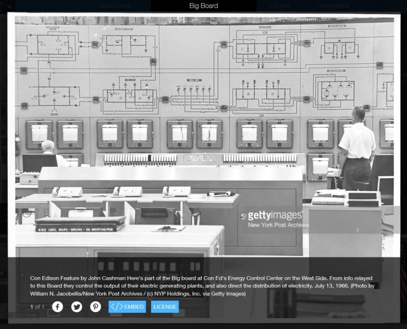
Here is a New Paper picture of the system in 1966- its is about the same today. To the lower middle left is 179th st, the lower middle is Bruckner/Hell Gate, to the middle right is Astoria West at the Top Astoria East at the Bottom.

Board1_zfmls3.jpg


Today its only two cables from 179th st to Astoria West, One cable via phase angle regulator at 179th to Astoria East.

All of it is a celebration of ring bus, which is VERY popular in the Northern USA. From the rings you have radial cables which may feed up to 5 transformers via disconnects only scattered through out the boroughs.
 
A zone of protection at Con Ed can include close to a dozen devices as we've discussed. On my own (for the educational fun of it) I've evaluated and have be drawing up the entire system being converted over to GIS and solid dielectric cables. Cross bonding at manholes and all. Here is my conceptual for Queens and Brooklyn. Notice the allure David, LOL [bigsmile]


IMG_0785_vrufxv.jpg


The circles with the R in them are SF6 breakers, easier to draw them that way when doing this by hand.

Obviously in and out going lines need to be alternated, I've got bus sections at 7-10,000 amps steady state. Need transfer buses, and "bulk" stations with over 12 positions 345-138kv are going to get a 3rd main bus on top of that.

But as seen in my iteration, every trafo, cable, PAR, reactive device, ect will have its own zone of protection with its own breaker. Two terminal cables only. Even stations like Leonard st in Manhattan would have a 138kv-161kv GIS mezzanine or interstitial with breakers.

Relay wiring and settings conceptuals are a breeze for me. I love this approach, its so much less error prone and reliable.

Cost would be something else, but its going to happen gradually soon or latter as the AIS equipment is well past its intended in service life.
 
David Beach said:
Protection must be designed to clear all faults in the zone of protection without reliance on communications. I've long, long considered line protection to be a pyramid.

I agree not just 100%, but 10,000%. I also consider line protection to be back-up remote line protection and both near + local backup busbar protection. Trafo/element protection where possible or practical.

You seen me here asking how I can get the most out of each zone.


We always get the base, stepped distance. I've come to the point of only using directional ground overcurrent when I have no better options and using ground distance anywhere I can.

Where are you encountering no other options that you must use directional over current?

That could be a lengthy thread all to itself, kind of a religious war, like iOS vs. Android, but suffice it to say that I've never added directional ground overcurrent to a relay with ground distance, but have a number of problems that I can't solve until the existing relays get replaced with ground distance capable relays.

Start a new thread, I'd love to read it.

I also want to ask you now- how is that ground distance even coordinates on T lines? I never understood that? Is is simply that a faulting line is simply one strand in a mesh such that more current is seen on the faulted line and less on all the parallel lines?


On top of that base layer I then lay a layer of Mirrored Bits DUTT/POTT/(BFTT/RDTL). Some places the third bit is breaker failure trip and other places it is remote drive to lockout and breaker failure results in a bit 1 direct trip together with a bit 3 DTL.

Awesome. You've got this covered!


Then if the stars align the apex of the pyramid is line differential. I've seen others that will hollow out the pyramid, but I can't think of any examples where we have.

Its possible the catch all zones of protection have something to do with it...

But David, you are lucky. I've seen your subs in docs and Google earth. Everything has a breaker. You're so lucky. You have it easy.

BTW, the world would be a better place without NERC or FERC. Cowboys like me do their own thing, singing Schiller's Ode-To-Joy.
 
Line terminals with protection older that then SEL-321 require the use of directional ground overcurrent. Might be EM relays or might be SEL-121/221G relays. Also still have directional ground overcurrent any place that hasn't had the settings reworked in the past 12 years or so. For most lines coordinating ground distance is pretty much like coordinating phase distance.

Mutual coupling does complicate things, but it also complicates ground overcurrent. Zero sequence is a mess, and there are lots of errors and uncertainties in the models; rho-earth is assumed to be a constant when Z0 is calculated but it is a continuously changing variable. Distribution neutrals need to be factored into the calculation but often aren't. Every Z0 error affects the reach of ground overcurrent. Every outage behind and in front of the relay changes the amount of ground current. As far as I can tell we historically ignored transformer out cases when setting the ground overcurrent. With ground distance the reach of zone 1 is only affected by any errors in Z0 of the line in question. Changes in in-feed, both behind and in front of the relay have the same sort of impact that they do for phase distance. Changes in in-feeds that change mutuals are more impactive than anything in the phase distance realm. But they also impact overcurrent.

One of the arguments in favor of ground overcurrent is resistive coverage. We use quad ground elements and the third forward zone has the task of not only reaching the remote end of all next lines but also covering a 50 ohm fault at the end of the protected line.

For the POTT scheme though, we do use directional ground overcurrent. But there we want to reach a long ways forward and even further reverse (SEL POTT scheme with a reverse block component). Forward at the local end and reverse at the remote end need to coordinate, but otherwise a fairly low setting works just fine.

I’ll see your silver lining and raise you two black clouds. - Protection Operations
 
David, have you ever used an Omicron line measurement unit?
 
Nope, no "measured" line impedances. But see if you can find the 2008 WPRC (Western Protective Relay Conference) paper In Search of Z0. Good hard ground faults at a known location can provide all sorts of information about system impedances.

The problem, as I see it, with things like the Omicron unit is that it can only measure the effective self impedance of the line. For positive sequence that's a great result. For a line out by itself it can even give you a good idea what the zero sequence impedance is, but start to through in mutuals and it fall apart.

Between loops and mutuals, I have one portion of the system where getting the right results requires accounting for the impact of one 500kV line (not ours), two 500/230kV transformers (also not ours), eleven 230kV lines (6 ours, 1 belonging to the owner of the 500kV, and 4 belonging to a third entity), five 230/115kV transformers (all ours) and nine 115kV lines (all ours). All twelve of the substations (of all three owners) fit in a 8.5 mile radius circle. That's never going to be "measured". But it can be empirically dialed in on.

What's fun is when you know exactly where the fault is, have reason to believe that the fault was low resistance, and see that a zone 1 ground distance element picked up for 0.25 or 0.5 cycles and dropped out you know exactly what the reach of that zone is.


I’ll see your silver lining and raise you two black clouds. - Protection Operations
 
From your experience I take it simple adjustments in zone reach (like a 150% zone 2) isn't always enough to compensate for mutual coupling.

Would you happen to know how or where underground cables stand in their measured vs mutual impedance? The concept above got me thinking again.

Part that always has me stumped is how to account for earth resistance. I've been told by some Engineers that the earth between any two points is always zero ohms and that any Z is purely that of the electrodes or fault point itself. However, actual relay data from uni grounded lines seems to indicate a fault near the substation produces values that of a multi grounded line; low impedance earthed, medium impedance earthed, high impedance earthed and totally ungrounded as you go down the line respectively regardless of the electrode or tower footing's measured resistance via test sets. I've never understood this. Why would total earth resistance vary more than that of grounding electrodes themselves?

Its almost like you need an MGN or 3/8 HS regardless.
 
We used to have several H subs, and now have added additional breakers to most of these stations. This change was driven by a combination of things including:
1) A desire not to have distribution customers interrupted for a transmission line fault.
2) A history of misops in the area we had the H configured substations. The misops may have had more with inadequate relaying than the breaker configuration.
3) Desire not to rely on remote clearing for transformer faults.
4) Removal of complicated autorestoration schemes that relied on MOD's.

The remaining H subs have been retrofit with line differential (SEL411L).

Mbrooke- What are MGN and 3/8 HS?

David- Can you say more about including distribution neutrals in the Z0? I had been under the impression that the earth ended up carrying most of the ground current, particularly over longer distances.
 
My mistake-

MGN = Multi Grounded Neutral

3/8 HS = lightning shield wire atop the pole or tower.

Can you elaborate in the inedequate relaying and miss ops? The complex auto restoration and how it was done? And with what relays/timers/controls ect. I'd like to replicate this- although I might (may) just end up using line breakers instead but I'd still like to know.

 
We run a multi-grounded neutral for the distribution system. Where feeders meet each other at open tie switches the neutrals are solidly tied together. The neutrals are also tied to the station ground grid at each substation with distribution transformers. So, what we have, in effect, is a system wide meshed ground grid at 24-30 feet above the ground.

If you dig into the Z0 calcs, the value of rho-earth determines the depth of the equivalent ground conductor. If rho-earth is small enough, the depth becomes negative. Maybe one could use a really small rho-earth and ignore the distribution neutral, but that neutral grid isn't uniform so it seems to make more sense to use the neutrals where they are and then find a meaningful rho-earth value. I've figured that for much of our system, for much of the year, 10 ohm meters provides a better match to observed results than the usual rule of thumb 100 ohm meters.

I'd imagine that a uni-ground system would have much less impact on the Z0 of an overbuilt line; if those neutrals weren't tied together between feeders they could probably be ignored.

I was disappointed that the paper at this year's WPRC that found great value in factoring in the distribution neutral didn't reference the prior work.

I’ll see your silver lining and raise you two black clouds. - Protection Operations
 
What is rho?


I'm sorry they didn't reference it- you've contributed so much with those papers.

By any chance do you have access your Z0 paper? I can't find it through Google.
 
Whoa! Now thats just gold! :)


And yahhh, I'm seeing your zones of Protection. Amazing how the two philosophies differ.

Do you also take water and gas mains into account?
 
David-Why do R0 and X0 go in opposite directions when adding a neutral? Adding a neutral to our typical subtransmission configuration takes Z0 from 0.52 + j2.33 ohms/mile to 0.35 + j 2.56 ohms/mile.

I am also surprised lowering the earth resistivity has a much larger impact on X0 than R0. Changing rho from 100 to 10 reduces R0 by about 10% and X0 by about 20%.

Mbrooke-Unfortunately I do not have the details for the old protection schemes, other than they used electromechanical relays. Prior to the installation of fiber, many of circuits probably did not have teleprotection.
 
Status
Not open for further replies.

Part and Inventory Search

Sponsor