jmacion
Computer
- May 10, 2022
- 20
Hello,
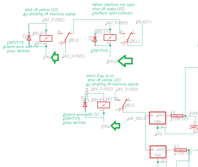
We have a device we are interfacing with that has an open collector input which are labeled as "pin2" and "INTLK" shown below. We are trying to activate a relay coil when the open collector pulls the coil down to 0V when its active. The problem we are having is that on about 1 out of 25 times we activate it, the RLY5 coil get stuck in the NO position and we can get it to return to NC even when powering down the whole system and then back on. Its confusing as we would think reset to the NC position? We know its not fused as periodically it resets itself and starts working again for another 25 or so runs.

We have measured the impedance of the open collector by putting a 2kohm resistor in series with it. We measured 8VDC over the 2k resistor which means the open collector is around 4kohm (has 16VDC drop over it). We thus assume that we cannot use a relay with a 24VDC coil (must activate at 19VDC) since we have a 24VDC rail and the drop over the coil will not be enough. We did replace the 24VDC relay with a 12VDC relay coil shown below and are having the same problem. What is very odd is that the original configuration was a DIN rail 24V coil Relay and this works 100% of the time, the part number is shown below.
Parts:
G5V1DC12: coil: 12.5mA/12VDC, R= 12/12.5=960ohm, must operate at 9.6V
G5V1DC24: coil: 6.3mA/24VDC, R= 24/6.3=3.8kohm, must operate at 19.2V
G5V1DC5 - we didnt try this one but shouodnt have to go any lower?
This is the DIN rail relay. I dont understand why it always works (for 6+ months).
Phoenix 2903370, 9mA/24VDC coil, R= 24V/9mA=2.66kohm. Minimum switch=5VDC
We have been building this circuit over and over and it still having intermittent behavior. We have built At least 4 PCBs with different parts changed out on each with no luck. There is no way the parts are damaged due to soldering as we have parts even on the PCB. We need help.
I am ready to break down and start crying on this one and return my college degree. Any help is appreciated.
Do we need a common emitter configuration to drive a relay (this cant be done as we dont control the source)?
thank you
Jim and Reshma
We have a device we are interfacing with that has an open collector input which are labeled as "pin2" and "INTLK" shown below. We are trying to activate a relay coil when the open collector pulls the coil down to 0V when its active. The problem we are having is that on about 1 out of 25 times we activate it, the RLY5 coil get stuck in the NO position and we can get it to return to NC even when powering down the whole system and then back on. Its confusing as we would think reset to the NC position? We know its not fused as periodically it resets itself and starts working again for another 25 or so runs.

We have measured the impedance of the open collector by putting a 2kohm resistor in series with it. We measured 8VDC over the 2k resistor which means the open collector is around 4kohm (has 16VDC drop over it). We thus assume that we cannot use a relay with a 24VDC coil (must activate at 19VDC) since we have a 24VDC rail and the drop over the coil will not be enough. We did replace the 24VDC relay with a 12VDC relay coil shown below and are having the same problem. What is very odd is that the original configuration was a DIN rail 24V coil Relay and this works 100% of the time, the part number is shown below.
Parts:
G5V1DC12: coil: 12.5mA/12VDC, R= 12/12.5=960ohm, must operate at 9.6V
G5V1DC24: coil: 6.3mA/24VDC, R= 24/6.3=3.8kohm, must operate at 19.2V
G5V1DC5 - we didnt try this one but shouodnt have to go any lower?
This is the DIN rail relay. I dont understand why it always works (for 6+ months).
Phoenix 2903370, 9mA/24VDC coil, R= 24V/9mA=2.66kohm. Minimum switch=5VDC
We have been building this circuit over and over and it still having intermittent behavior. We have built At least 4 PCBs with different parts changed out on each with no luck. There is no way the parts are damaged due to soldering as we have parts even on the PCB. We need help.
I am ready to break down and start crying on this one and return my college degree. Any help is appreciated.
Do we need a common emitter configuration to drive a relay (this cant be done as we dont control the source)?
thank you
Jim and Reshma
