Continue to Site

Eng-Tips is the largest engineering community on the Internet

Intelligent Work Forums for Engineering Professionals

  • Congratulations KootK on being selected by the Eng-Tips community for having the most helpful posts in the forums last week. Way to Go!

Removing basement column and splicing beams 4

Status
Not open for further replies.

mfstructural

Structural
Feb 1, 2009
229
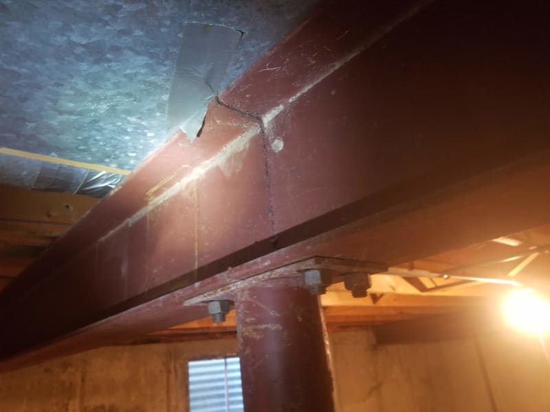
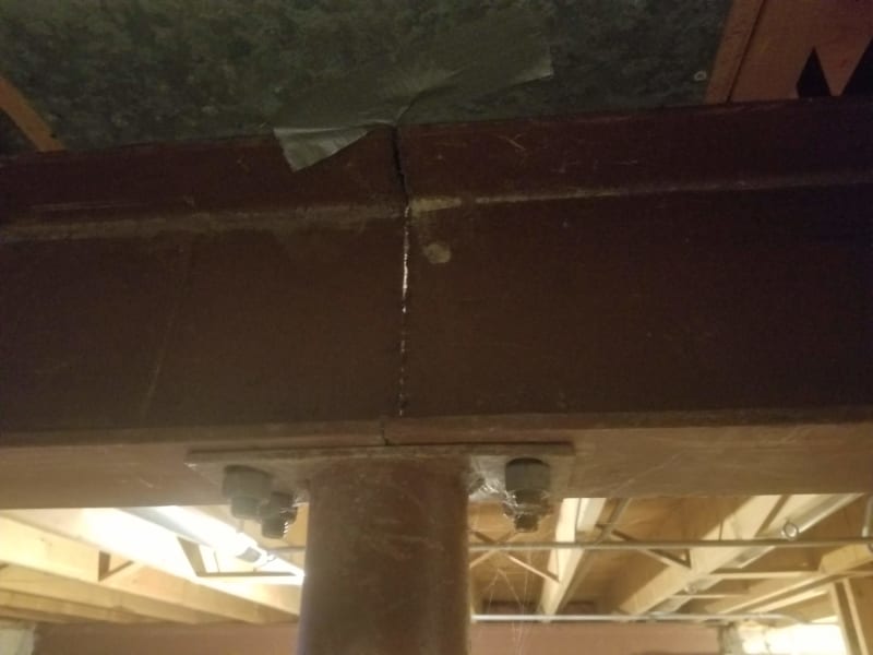
I'm sure this has been addressed here before. I have a project where the homeowner wants to remove a column under two abutting steel beams. The span from the wall to the column is 9' and then another 4' away there is a stud wall. I want to move the column within the stud wall (provide a circular footing). That will have the beam adjacent to the wall spanning 9' to the splice and the other beam will be cantilevering 4' over the column and its end will attach at the splice.

I haven't run numbers but wanted to get an idea of how people have approached these projects in the past. I was thinking of welding a channel to the bottom of the beam and also steel plates on each side of web. Heat is an issue during welding with wood joists bearing on this.

I've included a picture.
 
 https://files.engineering.com/getfile.aspx?folder=f57b56af-50e0-4d7c-bb33-9228298e156f&file=20200702_101420.jpg
Replies continue below

Recommended for you

It's tough to address reinforcing without knowing what's failing. Assuming that it's your new cantilever, I might weld WT reinforcing to the underside and make sure that the back span is tied down. This assumes that headroom and site welding are not deal breaker issues.
 
It is not worth even thinking about until you run numbers on a full-section beam w/o the column.
Also, is there another steel column buried in that wall that is out of our view? There may be no footing under that stud wall and the beam is designed to span column to column. Seems unusual to have a steel beam on top of a stud wall and have the wall be intentionally load bearing.

If this was mine, and a footing existed at the end of the stud wall, I would probably suggest installing another beam underneath if headroom allows - bearing one end on the stud wall and the end bolted to the concrete wall with a plate. (stability would be a concern)
Could also just add some shoring and cut and remove the existing beam and replace it.
 
Consider the famous architect, Frank L. Wright. In his house he needed the clear space,so removing the column went. So the ceiling sagged some, so what?
 
It doesn't look like the beam is spliced over the column, so maybe it's a continuous beam. You might have to reinforce the 13' span.

BA
 
OG,

How do you know the sagging ceiling wasn't the effect that Wright wanted?:) The trouble is the floor has came down as much as the ceiling.
 
Thanks for everyone's input. Sorry for the delay, I have just recently begun digging into this.

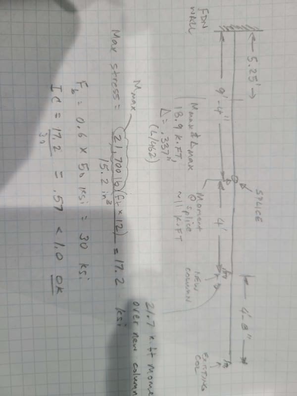
The beam is a W8x18. The new configuration consists of 2 spans. Span on left will be 13' and the span on right will be 5'. The column to be removed is currently located 9'-4" inches from left (where the beam bears on the foundation wall). I modeled the new configuration and it has the maximum moment of 21.7 k-ft occurring over column between the two spans, which makes sense. The highest moment in the left span occurs about 5.3' feet from the left and is about 19 k-ft. The maximum deflection of .337" under full D+L occurs near this point also which makes sense. The moment at the location where the column is being removed and the two abutting beams need to be spliced is 11 k-ft.

Because the left span is relatively longer there is uplift on the connection at the right end of the right span. The maximum uplift is .934 kips. I'm not sure how to address this, the beam at the right end of the span is bolted to the one side of the cap plate over the column with 2 bolts. I think it is ok since at the location where there is uplift there is another beam from the adjacent span bearing on the column also. This will offset a lot of the uplift .

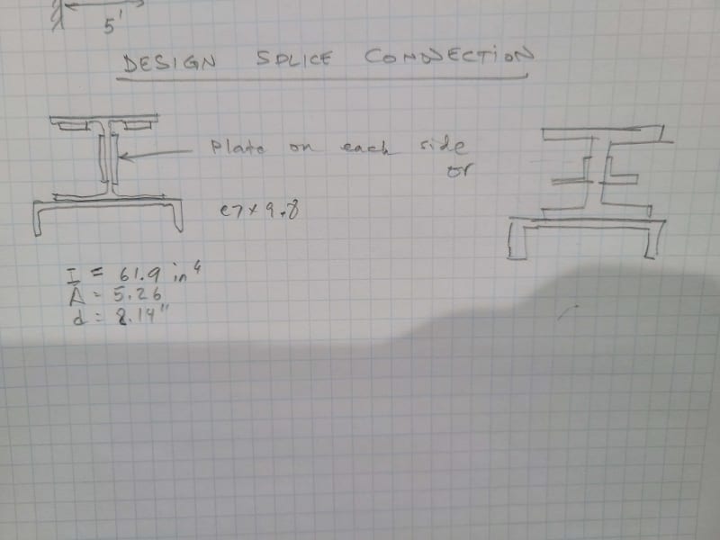
My last question is regarding the splice connection. So I have a W8x18 and am planning to weld a channel to the underside of the beam and a plate on each side of the web. The problem is with the top flange. There is a piece of sheet metal on the bottom side of the joists over the beam where the column is currently located. That will have to be removed. If there is joist there I think I can place and weld a plate on top of the top flange, but i suspect there is a joist and that won't be the case. Another option is to weld a plate or angle (I think an angle will be sufficient) to the underside of the top flange. The plate would be close as possible to the fillet where the web and flange meet and be welded at that point and also to the flange at the end of the beam. As far as design goes is the best way to do calculations to decouple the moment about the height of the beam and design welds and local stresses in reinforcing steel for these forces?

I included some more photos

Thanks

Steel_Beam_Wheaton_x0mazc.jpg


Steel_Beam_Wheaton_2_k2f2zk.jpg


Wheaton_Beam_Sketch_vklg6n.jpg


Wheaton_Reinforcing_rgwza7.jpg

 
For your stated moment (11 k-ft), 2 - 1" plates from inner top flange to bottom flange will work. You need to ensure adequate development length on each side of the splice plane.

You may try thinner plate, if deflection due to variation in beam stiffness is acceptable.
 
Okay, the beam is not continuous over the existing column.

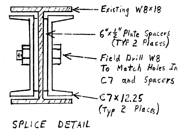
For the splice, a C7x9.8 on each side of the web would be close, but doesn't fit perfectly snug. A combination of plates and angles as shown below might be better.

Uplift at the right end of the beam will be partially offset by an existing beam reaction and partially offset by column tension. It may be advisable to adjust the column base connection to allow for a slight upward deflection without ripping anchor bolts out of the concrete.

image_csh0fr.png


BA
 
Good detail, SRA. It is neat and compact. I like it very much.

BA
 
SlideRuleEra,

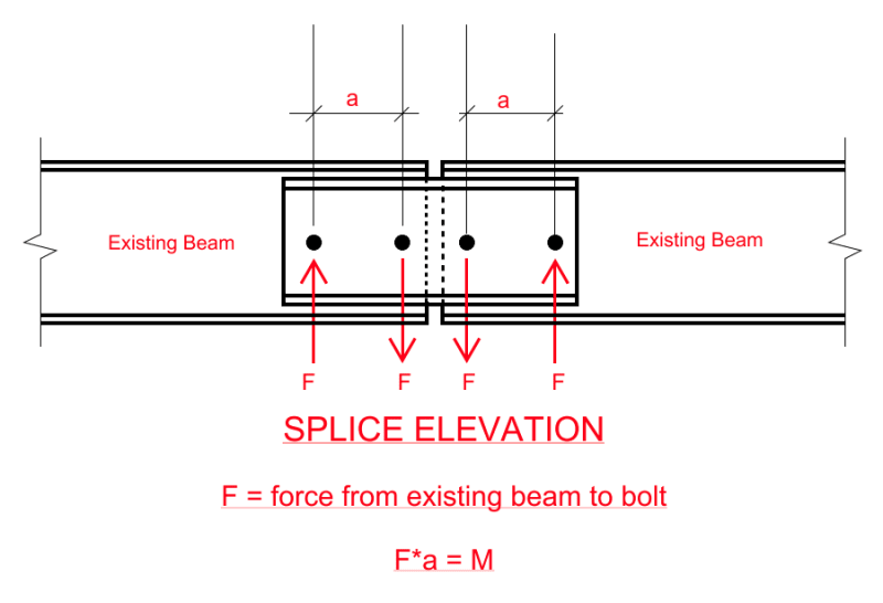
Using your splice detail, I have sketched the elevation below. Since the channels are not welded to the existing beam, the minimum number of bolts is four, correct?. You specified C7x12.25, but I believe that C7x9.8 would be adequate, agreed?

image_aukxkg.png


BA
 
BA - Agreed, four bolts minimum.

No doubt the C7x9.8 is adequate; there is little difference in the structural properties of any of three C7 sections. However, the biggest difference, to me for this application, is web thickness. The C7x9.8 web is 3/16" thick, the C7x12.25 is 5/16". Since the W8x18 web is 1/4" thick, did not want the any less than 1/4" web for the channel.

Edit: If MC6x15.1 are used instead of C7, my proposed detail can be simplified by eliminating the 6" x 1/2" spacers.

[idea]
 
You show a fixed support condition at the foundation wall in your calculation, I'd double check that. This being a residential basement beam it's highly likely that the beam was set in a bearing pocket and then packed around with grout, so for analysis purposes is much more likely a pinned condition.

My Personal Open Source Structural Applications:

Open Source Structural GitHub Group:
 
I didn't notice any bracing/connections to the top flange of the WF. I'm used to seeing a nailer bolted or lagged to the top flange of the WF and the wooden floor joists secured to the nailer to reduce the unbraced length of the top flange. Am I missing something? Those floor joists seem to be free floating.

It seems to me that if you are increasing the free span, the reinforcement would have to extend long enough along the length of the beam to keep the deflection with allowable limits and to prevent the floor from becoming a trampoline.

For easy of installation, BAretired's solution appears be the easiest. Keep the web plates about two inches from the top and bottom flanges so the welder can access the edges of the plate to weld them to the beam web. As far as that goes, a few plug welds to secure the web plates to the beam web would probably do the trick. Most of the loads can be transferred from the angles to the beam by the welds securing the angles to the web plates and the beam flanges. As for the welds to the underside of the top flange, place the welds where there is no wood directly above the welds. The individual pieces wouldn't be as heavy as a length of channel unless there is plenty of manpower to horse the steel channels around. A couple of hours with a welder to secure the plates and angles and you would be good to go.

A water hose should be kept handy just in case.

Best regards - Al
 
Status
Not open for further replies.

Part and Inventory Search

Sponsor