Continue to Site

Eng-Tips is the largest engineering community on the Internet

Intelligent Work Forums for Engineering Professionals

  • Congratulations waross on being selected by the Eng-Tips community for having the most helpful posts in the forums last week. Way to Go!

Removing wall below a 30' roof truss

Status
Not open for further replies.

mfstructural

Structural
Feb 1, 2009
229
I took a look at a residence last week for a client looking to remove a wall below a roof truss spanning 30'. From my experience these single-story homes with 30 foot spanning roof trusses are self supporting and do not require center supports. The thing that threw me off on this one was the center web member that was typically vertical and was connected to the peak was not vertical. It was was oriented at an angle to the vertical. I included pictures below.

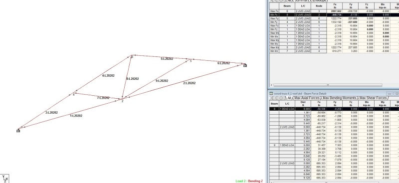
I created a model of the truss and found that the largest compression force in the top chord is 2097 lb, max tension in the vertical web member chord is 448 pounds. The tension in bottom chord is relative low. My calculations show that a 9.5' long 2x4 can take 2600 pounds of compression. this is the governing member.

Based on my analysis, a center support, i.e., bearing wall is not required. I did not check deflection yet. I think that would be a concern. I guess my question is why would vertical web member be skewed like you can see in the pictures.

The reactions I calculated by hand are within a couple percent of the models.
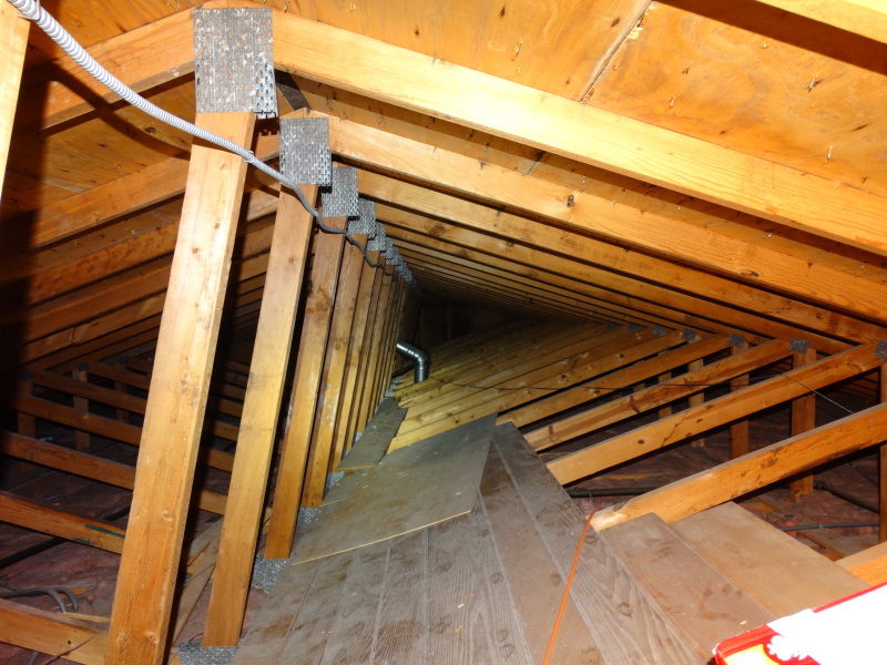

DSC06682_icdnz9.jpg

staad_screenshot_jnjzta.jpg
 
Replies continue below

Recommended for you

I would argue, if that bottom chord panel point is directly above the wall, that the original intent was for it to be load bearing, regardless of whether it could clear span or not. Otherwise the skewed web member makes no sense.
 
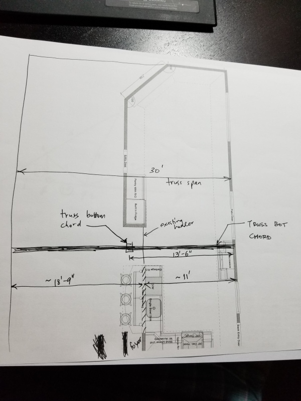
The bottom panel point is not directly below the panel point. There are several walls staggered inside the kitchen, foyer, and living room. I attached a sketch. Would they bear a bottom chord on a wall where a panel point is not located?

20170518_135300_cycwp8.jpg
 
Mfstructural:
Why does your sketch/model show the right reaction point much higher than the left reaction point? Is that a fact, the photos seems to show a horiz. bot. chord. Also, why doesn’t your model show the vert? web members btwn. the top chord and the bot. chord members. The ridge in that part of the bldg. is obviously not centered btwn. the two reaction points and they wanted a web member to go up to the ridge. Then, they wanted the two top chord members (slopes) to be supported at about their mid-points; and also they wanted the bot. chord supported at about its mid-points. Then, they would have looked at stock lengths of materials for any required splices vs. location of the joints and nailer pls. Then, it is just plug and chug with their design software, and your first look seems to confirm things are o.k. The truss manuf’er. would not likely design for a real bearing point removed from a node point. What some carpenter might do with the wall below is another matter. With that truss you might as likely, as not, get some truss uplift during the winter seasons.
 
It would be possible that they relied on the bottom chord in bending. Unlikely, but possible. If the ridge lines up down the middle of the truss, they may have intended on flipping the trusses 180 degrees to have that panel point above the wall to accommodate the jog.

I also believe that the truss designers consider the top chords laterally braced thanks to the sheathing/strapping, therefore the slenderness limits noted by SRE wouldn't apply.
 
The geometry of the truss in the program sketch does not appear to correspond with the geometry shown in the photograph, in particular the slope of the top chords.

I agree with SlideRuleEra that 9.5' is too long for a 2x4 in compression.

I would also agree that the wall, if bearing, should be at a truss panel point but sometimes structures are not built as they should be.

BA
 
Assuming the wall was indeed used as bearing, I would expect removing it will change the required plate sizes. Mainly plate grip will fail in this scenario, since truss design software will spec a minimum plate size for each joint. (Software also checks plate cross section bite on member, metal strength, etc.)

The bot chord joint being not directly above a wall does not rule out the wall being used as bearing, although it does make it much less likely. As was mentioned, the joint is likely placed at the center point of the bottom chord (measured along the rake). I can guess that moving the joint to the right would have necessitated another joint in the bottom chord on the left side.

OTOH the "existing header" labeled in the sketch above would lead me to believe that they did design for a center bearing. Maybe they designed the truss for a bearing at either of the two center locations. It's possible - not a great idea just to save making two different truss types, but it's possible.
 
@jayrod12,
I assumed that SlideRuleEra was referring to the internal diagonals, not the top chords. I would agree that the top chords are continuously braced along one edge but the diagonals should have a bracing member at midspan.

BA
 
As a former truss designer/builder, I have the following to offer on this one:

jayrod said:
if that bottom chord panel point is directly above the wall, that the original intent was for it to be load bearing, regardless of whether it could clear span or not. Otherwise the skewed web member makes no sense

Absolutely. The skewed king post would kill the symmetry on two webs and four joints. It would also make the install less dummy proof. All that costs money in a commodity driven industry where margins are non-existent. Most manufacturer's wouldn't do such a thing unless there was a good reason for it. Other than the center bearing, the only other thing I can think of is if they were trying very hard to use up some scrap material creatively.

OP said:
From my experience these single-story homes with 30 foot spanning roof trusses are self supporting and do not require center supports

Yes and no. Absolutely a 30' clear span truss is doable without a lot of fuss. That said, it's a healthy span and the center bearing might be the difference between MSR chords and two and better. The design might also have fallen to a particularly conscientious designer who worried, like you, that a presence of available bearing would cause bottom chord bending issues if a panel point was not provided at that location.

OP said:
Would they bear a bottom chord on a wall where a panel point is not located?

With the advent of software, folks are getting a lot more adventurous with their wood truss designs. We see evidence of that on this forum regularly, for better or worse. What might have happened here was the designer may have wanted to pick up the bearing but, due to the realities of production economy, wanted to use one configuration for the entire run. So he/she may have put the bearing someplace close and either a) designed the bottom chord for the implied eccentricity or b) simply ignored the eccentricity.

jayrod said:
If the ridge lines up down the middle of the truss, they may have intended on flipping the trusses 180 degrees to have that panel point above the wall to accommodate the jog.

Possible but unlikely. Even when the ridge is centered in theory, it won't be centered within the trusses in practice. Flipping the trusses can mean shifting the ridge back and forth along the run which will have contractors calling for blood.

I like to debate structural engineering theory -- a lot. If I challenge you on something, know that I'm doing so because I respect your opinion enough to either change it or adopt it.
 
If the interior wall is a support then 1 giveaway would be that the wall plate/beam/metal wall hanger the truss is sitting on is beveled to have full bearing contact with that interior joint. Another thing to look at is the sizes of the heel plates (where the top chord and the bottom chord meet), those usually are bigger plates than your interior joint plates if there is no interior support. If there is a support in the middle then the heel plates would be relatively small. Hope I am making sense.

 
Yes, with my calculations I was considering the 2x4 braced at 2' in compression because of the roof sheathing. If the compression ratio was exceeded in my calculations, wouldn't it have been exceeded when the truss was designed? codes may have been different, but technically the configuration hasn't changed.

dhengr: I do have the vertical web members in the model that was a screenshot of an earlier model I did, my mistake. Also, my reactions at the two ends are equal when I look at them in the model.

Based on all the discussion here and the uncertainty of the intent of the original design, I think designing a new header to support the trusses across the new opening would be the way to go. Another thing I was thinking of doing, in case the homeowner doesn't want a header causing a loss of headroom, was to install an LVL on the top of the bottom chord, strapping it to the bottom chord. The LVL would extend over the portions of the trusses that were supported by the walls remaining.

I think not knowing the original intent because of the skewed vertical web member is a good reason to go with the route to support the trusses near midspan.
 
Just want to say thanks for all the responses and I will be recommending installation of a header/support above truss.
 
We were thinking of putting a hole in the drywall since they're renovating anyways. It's about 11' long.
 
Status
Not open for further replies.

Part and Inventory Search

Sponsor