Eng-Tips is the largest engineering community on the Internet

Intelligent Work Forums for Engineering Professionals

Reporting A Unilateral Surface Profile Tolerance

Status
Not open for further replies.

DJ Nelson

Aerospace
Oct 2, 2023
7
0
0
US
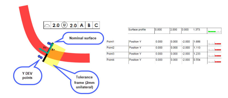
We have a surface with a profile of .008 U .000 to ABC.
we measured the surface with a scanner after aligning to the Datums.
We ended up with a MIN of .0072 and a max of .0121 the software calculated the measured Profile as .0322
I am not sure if I do not understand how this is calculated and reported but it seems questionable see Attachment
If correct or incorrect were can I find were it is that explains how to record this.
 
 https://files.engineering.com/getfile.aspx?folder=b06442da-d939-4a55-9a6a-44eeba77027f&file=Surface_Scan_Feb_23_2024.pdf
Replies continue below

Recommended for you

Good morning all,
I'm working with a surface profile which uses the UZ modifier. The results reported I'm struggling to make sense of.

The element is dimensioned with: |⌓|2.0 UZ 2|A|B|C| in 2 positions.
My "A side" I have a reported value of 1.974 (Element constructed with x4 points in each corner) Y Axis deviation points for each of these are .065/.013/.181/.203
My "B side" I have a reported value of 5.382 (Element constructed with x4 points in each corner) Y Axis deviation points for each of these are 1.691/1.117/1.238/.557

I've used the calculation mentioned above which seems to conform with my results on the B side t(2) + 2g(2x1.691) // 2 + 3.382 = 5.382

For the A side the only way i managed to tie the numbers together was recognising from all 4 points none would be out of tolerance if multiplied by 2. I then us the lowest deviating point [0.013] and minus this in the calculation as t(2) - 2g(2x.013) // 2 - .026 = 1.974

Some how it ties in, I'm not sure if this is the right calculation - Can anybody make sense of what's happening with these numbers?

Working to ISO Standard

Thanks in advance
 
J-Hendry,

To begin with, the big thing to realize here is that unequally disposed profile callouts work differently in ASME and ISO; |profile|2(U)2|A|B|C| in ASME does not define the same tolerance zone bandwidth as |profile|2 UZ 2|A|B|C| in ISO.

As an example, if a nominal flat surface is at Y=0 and the material is below 0, then:
- the above ASME callout defines a tolerance zone that is between Y=0 and Y=2.
- the above ISO callout defines a tolerance zone that is between Y=1 and Y=3.

As a consequence, the same measured points may result in a different actual profile value depending on the standard used.

The discussion in this thread has been based on ASME so far.

Question to you: Do you know what the Y deviation values represent in your case?
 
3DDave said:
the (U) notation has been endlessly confusing. I voted against it, but the vote at the committee meeting was a pre-arranged deal
In the past you've railed pretty hard on how awful the ASME standard is. But here you say that you're on the committee? That must make for interesting meetings when things are stacked against you like that :)
 
Pmarc. I recognise there is a difference in the meaning between the standards. After highlighting this point with our designers i believe they didn't recognise the calculation is different.

In reference to your comment on how this should be seen in ISO - Is it this way only? As i've seen Unilateral and Unequal bilateral both detailed under the UZ symbol.
The intention for our design team is only negative 2mm is considered in this evaluation.

Slight oversight by myself on the Y dev points... I just noticed these are all set to absolute which was throwing my head completely!

I have my contact @ Mitutoyo coming to see me next week to further discuss this and confirm my setup is correct.
 
Garland, I did not say I was on the committee. I was at the vote. The meetings are open to the public, as was the voting, though the deliberations among members outside of the meetings are not.
 
J-Hendry,

Yes, unilateral and unequally disposed tolerances are both defined with UZ in ISO. Unless you want to define a tolerance zone with an undefined offset from the theoretically exact feature - in that case OZ is used.

The fact that the Y dev values are all positive is indeed a key problem to understand what is going on here. I assume they represent a distance of the point from the profile tolerance zone boundary.
 
3DDave,
Ah... my apologies. But that's a pretty strange policy to let anybody from the public vote on these things. I assume it's just an advisory vote and then the committee does an internal vote to determine what goes into the Y14.5 standard.
 
Garland,

I don't recall if my vote was one that was counted or if it was "my vote" as I indicated the symbolic use and the vague indication of the direction of asymmetry could have been eliminated with +/- variation directly in the FCF. It took the CAD company we spent large amounts of support dollars to about 5 years to add the (U) to the palette, +/- were already there.

Anyway, the official vote did take place at that public meeting, but as mentioned, they'd already spent so much non-reviewable effort at that time that it was a formality.

No problem; the opacity of the real proceedings and the large cost to keep up with the public ones means, almost by design, a disinterest in public comment.
 
Apologies Pmarc, i didnt explain properly on the Y dev points.. Yes, i am shifting the Co-ord to the planes origin and then rotating meaning Y DEV's are each points offset from the face
 
J-Hendry,
No need to apologize.

Are you able to prepare a rough sketch showing the nominal surface, the tolerance zone disposition relative to the nominal and the measured points with Y devs?

Thank you.
 
I think this covers everything I'm seeing my side.(Symbol is current being updated from design team - This should read as UZ) If you need any more info let me know.

Surface_profile_-_Evaluation_unev9d.jpg
 
I am not sure I fully understand what I see but I am pretty confident that the tolerance zone in yellow does not represent the |2 UZ 2| requirement in ISO. Otherwise, it should be offset further by 1 in the minus Y direction.

The tolerance zone matches with how ASME defines it.

Assuming the numbers in the second column from the right represent Y deviations, then for the set of 4 numbers shown, the actual profile value should be:

2(tol value) + 2x1.686(max dev) = 5.372 per ASME

[2(number after UZ) + 1.686(max dev)]×2 = 7.372 per ISO
 
pmarc,
Should I understand that in ISO GPS a specification such as
|profile|2 UZ 0|A|B|C| does not make any sense?
Or better to say to is equilavent with |profile|2|A|B|C|?


greenimi,
Yes, specifying UZ 0 after the tolerance value does not add a value because the number after UZ defines the offset of the tolerance zone center from the theoretically exact feature.
 
pmarc said:
I am not sure I fully understand what I see but I am pretty confident that the tolerance zone in yellow does not represent the |2 UZ 2| requirement in ISO. Otherwise, it should be offset further by 1 in the minus Y direction. The tolerance zone matches with how ASME defines it. Assuming the numbers in the second column from the right represent Y deviations, then for the set of 4 numbers shown, the actual profile value should be:
2(tol value) + 2x1.686(max dev) = 5.372 per ASME
[2(number after UZ) + 1.686(max dev)]×2 = 7.372 per ISO

Pmarc,
My follow up question is: how did you calculate the "reporting" ISO value since, as far as I know, ISO does not have a reporting standard?
Did you calculate it just using the Y14.5.1 concept?

I am trying to understand your thinking and I am NOT saying the above numbers are incorrect.
 
I am not aware of an ISO standard on reporting profile tolerance values either, but the number I got is the the most natural candidate for the actual value.
 
Pmarc,
Thank you for your answer.
If that's the case then I think for the sketch provided by J-Hendry I need some explanation, as it is not very clear to me your numbers.

ASME Profile |2 U 2|A|B|C| is translated into ISO as profile |2 UZ +1|A|B|C| doesn't it?

Now, per the ISO GPS provided skecch profile |2 UZ 2|A|B|C| which can be translated into ASME as Profile |2 U 3|A|B|C|
then the closes boundary is 3-1.686 = 1.314

So your numbers become:
2(tol value) + 2x1.314(max dev) = 4.628 per ASME

[2(number after UZ) + 1.314(max dev)]×2 = 6.628 per ISO

Why "my numbers" are not correct ?

 
pmarc said:
Sorry, but I don't understand where the |2 U 3|A|B|C| comes from.

I am trying to translate from ISO to ASME, beauce in ASME we "know" how the reporting should look like.

So per J-Hendry latest email about his "engineers" agreeing to add UZ (instead of U) in the profile callout, then the callout become ISO
Therefore, profile |2 UZ 2|A|B|C| I was "trying" to translate in ASME

By the way what is the correct translation of profile |2 UZ 2|A|B|C| to ASME ?
Is not |2 U 3|A|B|C|?
If not, then which is?

 
Status
Not open for further replies.
Back
Top