Eng-Tips is the largest engineering community on the Internet

Intelligent Work Forums for Engineering Professionals

Resin Anchors in a Blockwork Wall. 1

Status
Not open for further replies.

Abuh001

Civil/Environmental
Jan 24, 2018
28
0
0
GB
Hi All,

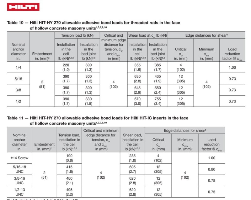
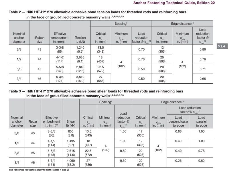
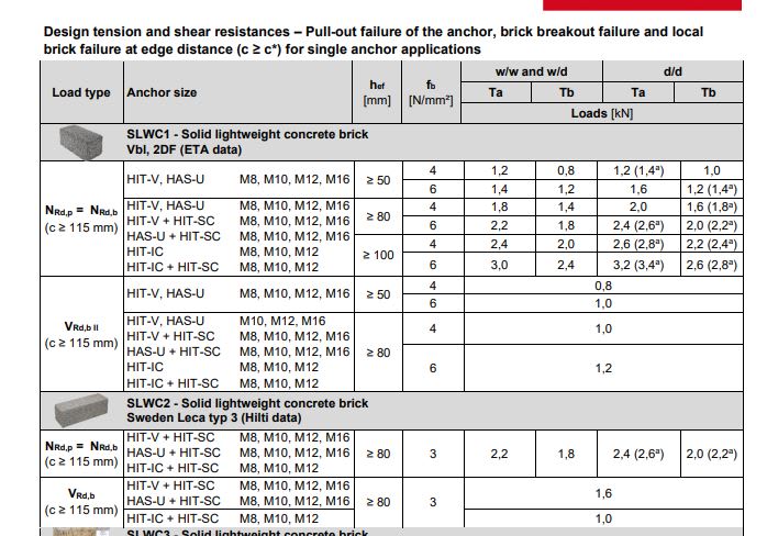
I hope you are doing well. Recently, I have ]been getting involved with trying to support a beam off a 100mm blockwork wall using resin anchors. The load on the beam is a modest 10KN. However, having looked at both the guides for Hilti and Fisher the allowable shear force force on a 12mm resin anchor set in lightweight blockwork of strength 3.6N is 1KN or less. This doesn't sound right. An 8mm bolt in in 47mm of C16 timber (against the grain) gives a bearing value of this much (1.13KN). What are your thoughts? How do you design resin anchors set in masonry.

Hilti_Anchor_Strength_wop5hd.jpg
[img
Thanks.
 
Replies continue below

Recommended for you

Firstly I think you've posted the tension loads and not the shear loads. Even so, there are many and varied failure modes for masonry and it's usually the masonry that will fail before the anchor.

I am comfortable using resin anchors for systems (e.g. a ledger plate to support joists) where there are multiple anchors and if they failed the floor would deflect but not be likely to imminently destabilise the overall structure. I'd be unwilling to use resin anchors to support a beam which is presumably supporting other parts of the structure, at least without load tests and another secondary redundant load path.

It is trivial to get a concrete saw and cut a pocket for the beam to sit directly onto a wall.
 
Have you tried using Hilti Profis Anchor Design software as a secondary check? I feel that the book is more onerous with the SWL as opposed to the software where Edge distances etc come into play
 
You mention blockwork but posted a table for bricks. I assume you're going into grouted or ungrouted CMU here?

In the case of ungrouted CMU, the values are definitely low and really only relied upon for trivial loading.

Hilti1_jdkptp.jpg


Usually our go-to when we need more capacity is to chip the face shell and grout the anchoring locations as well as several adjacent cells.

Hilti2_zybcck.jpg
 
How is the beam supported? Do you know your tension and shear values? Do you understand how anchorage into CMU works?

If you can answer "yes" to all of there, the design should be a snap.
 
Hi all and thank you for your responses.

I do believe the tables posted contain shear and tensile capacites for the anchors.
The concrete blocks are solid and are going to be ungrouted.

The beam is just supporting a garage roof. It is a timber beam of Length 4m. The reaction load is around 10kn. Normally I would spec a heavy duty Simpsons joist hanger with 4M12 resin anchors and be done with it.

On this occasion, I decided to check the capacities and they just seem incredibly low.
Just seeing if anyone else is of a similar opinion or is it just me?


Thanks "JLNJ".

The beam is simply supported. I know the shear value. It's 10kn. Could you kindly assist on how the design would be carried out.

Thanks
 
Abuh001 said:
I do believe the tables posted contain shear and tensile capacites for the anchors.

Indeed they do - I'd been looking on my phone when I'd replied so misread it.

You will need to try the Profis software - not least because the group effect of the anchors should be considered.

Although I stand by my original suggestion of cutting a pocket for the beam to sit onto. Hard to beat direct bearing.
 
Does the beam sit on some sort of a bracket? If yes, are the prying forces accounted for? Do you have combined tension and shear loads?

Providing a sketch of your actual condition will help us provide better, more specific, answers. Otherwise we are just guessing.
 
Status
Not open for further replies.
Back
Top