Continue to Site

Eng-Tips is the largest engineering community on the Internet

Intelligent Work Forums for Engineering Professionals

  • Congratulations SSS148 on being selected by the Eng-Tips community for having the most helpful posts in the forums last week. Way to Go!

Restraint / Equivalent stabilizing forces and load paths

Status
Not open for further replies.

Eagleee

Structural
Feb 14, 2017
51
Hi everyone,

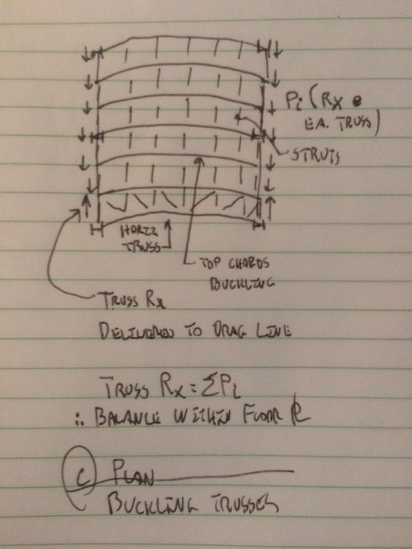
I am interested in your opinion on the general way of dealing with stabilizing forces. Imagine a simple industrial steel structure, with roof trusses where the compressed chord(s) is restrained from buckling out of plane by struts (purlins or roof cladding assumed not to do this). These struts usually transfer forces to the roof bracing system.

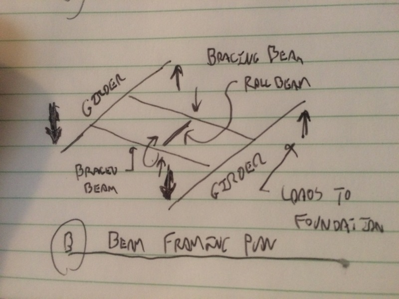
1. As 2nd order analyses are not usually performed, the compression + out of plane imperfection of the chord is usually taken into account through an equivalent uniform lateral load applied to the chord. Here I introduce my first question: the application of this lateral load is made together with the application of 'reactions' in the eave struts (assuming the truss is laterally supported there), right? So in this situation, the axial force in the eave struts will be opposite of that in the intermediate struts. Is it correct that as long as everything is connected to the bracing system, no load originating from this situation will leave the roof plan?
2. Since the applied 'fictitious' load is a fraction of the max. compression in the chord, how would it enter in load combinations?
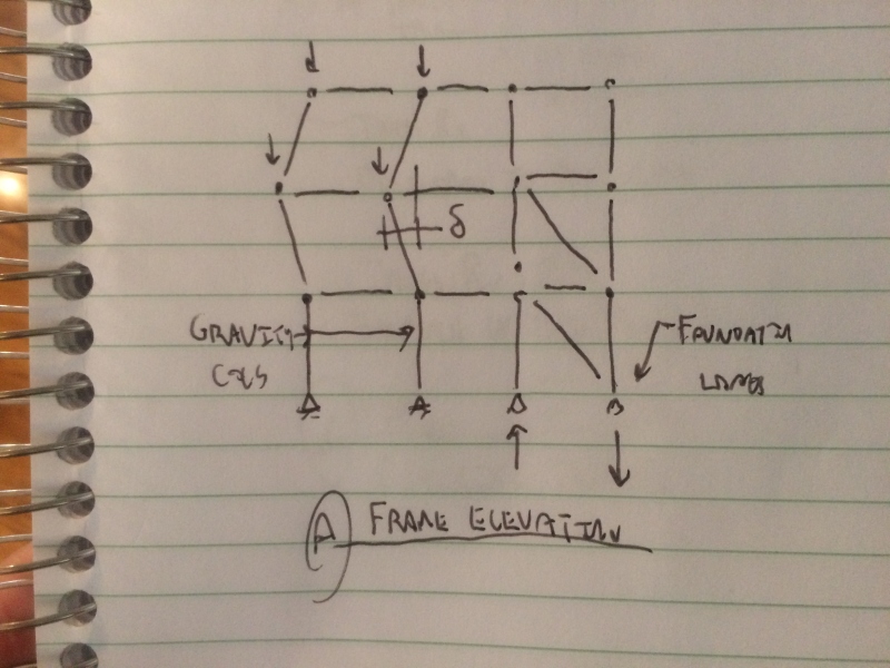
3. Have you encountered cases in which a strut which is assumed to restrain the compression member is not connected to the bracing system and would transfer the force to the top of a gable column for instance? If so, I guess the force would indeed make its way down the structure and it will influence the design of other members (I am exaggerating the magnitude of these forces to illustrate my point), would you agree?

I have little experience under my belt, but from what I know, these forces are dealt with in practice just by ensuring that the struts meet the stiffness and / or strength criteria (i.e. the 2% rule) and leaving a small reserve for the bracing system, is that correct?

All in all, if I would have to sum up my questions into one, I guess it would be: "where do you stop with these forces and how do you see their paths?". I could also provide a quick sketch if the situation I am referring too is unclear. Thanks a lot in advance, hope it's not too much text.
 
Replies continue below

Recommended for you

I see what you're getting at. My take:

1) Without question, the load in a girder kicker brace in the roof of a fifty story building has to somehow make its down to to the foundation through dozens, if not hundreds, of other members. That's just load path, no getting around it.

2) Were one to include bracing loads in the global structure load cases, I think that it would be rational to split the bracing force requirement to the different load cases in proportion to the various external loads creating the bracing demand. This would be a ton of work, however, and I've never known anyone to do this in practice.

3) In practice, in general, I do not see engineers including local bracing demand forces in their global structural models. That would add a great deal to the modelling effort to capture an effect that is usually of very little consequence a step or two further down the line.

4) In practice, at least 90% of the time, we seem to only check the braces themselves, and their connections, for the required bracing forces. Much less commonly, engineers will check the members two or three steps back into the load path. It's a judgment call dictated by the nature of the subsystem that one is investigating.

5) As with most things, there are exceptions. I got started designing wood trusses. If you get a run of 50 identical trusses on a commercial roof, the cumulative compression web bracing forces at the end of the line can be upwards of 1000 lbs. That's real load in light frame construction. And, if you've ever witnessed the production of said trusses, you'll know that it's highly probable that all of the webs will want to buckle the same way.


I like to debate structural engineering theory -- a lot. If I challenge you on something, know that I'm doing so because I respect your opinion enough to either change it or adopt it.
 
I'm going to really stick my neck out, and disagree with KootK on this, mainly his comment #1.[ ] The force the brace is required to carry is certainly real.[ ] But consider a free-body diagram for the brace.[ ] It simply has an axial force applied to it at one end, and an equal-and-opposite axial force applied to it at its other end.[ ] These two (very real) end forces are "produced by" localised structural behaviour in the vicinity of the attachment points.[ ] If the two attachment points are relatively close to each other "in structural terms" (whatever that actually means) then the pair of end forces that the brace applies to the rest of the structure will cancel each other out within the local area.[ ] Saint Venant's principle tells us that there is no need for a load path to the foundation.

KootK's point 5 is correct where it applies, and you will get a "cumulative" bracing force to be resisted.[ ] But, depending upon the overall structural configuration, it is still possible that this cumulative force will be resisted at least in part by the multiple component brace reactions in the overall roof system.[ ] One big northbound force partially countered by multiple smaller southbound forces.

OK.[ ] There's my neck.[ ] Bring out your axes.
 
Denial said:
OK. There's my neck. Bring out your axes.

Mmmm... fresh jugular. Interesting critique.

Certainly, in addition to my prior comments, I would agree that the following statement is true:

6) Stability demands of this sort are internal actions. As such, there is no net load on the structure as we see with external actions. That said, in many cases, the load only cancels out when one considers an FBD that encompasses a good swath of the structure, perhaps including the foundations and, occasionally, the soil. Sketches A & B below are common examples of this phenomenon.

For illustration and discussion, I submit the three examples sketched below. They are:

1) The ubiquitous example of building gravity columns braced by a vertical truss. Load makes it to the foundation.

2) A floor or roof beam braced against lateral torsional buckling via attachment to its neighbor. Load makes it to the foundation.

3) Braced truss top chords sans shear diaphragm which I believe to be the particular case of interest to the OP. Loads get passed around some but may be resolved within the framing level under consideration. Kinda depends on what you've got going on for lateral restraint of the deck.

When you broached this issue, I imagine that you had a particular counter example in mind (or several). I'd welcome the opportunity to evaluate those examples if you're willing to share it/them.

Capture_01_tbhaou.jpg

Capture_02_hyg2ls.jpg

Capture_03_zwchqs.jpg


I like to debate structural engineering theory -- a lot. If I challenge you on something, know that I'm doing so because I respect your opinion enough to either change it or adopt it.
 
Thanks for the great answers.

KootK said:
In practice, at least 90% of the time, we seem to only check the braces themselves, and their connections, for the required bracing forces

Are you here referring to forces arising from a 'local' non-alignment of 2 members (as for instance you illustrate on the first sketch in your last post), or from the forces arising from the 'global' imperfection of the restrained member(s), that you illustrate in the third sketch, or both?

I was indeed referring to the situation shown in your third sketch. So in the case that you show, the inner struts will be in tension and the eave struts will be in compression. And the horizontal truss, if stiff enough will carry all these loads which will not move downwards. The simplest way this issue can be rephrased, in my opinion, is: will there be horizontal reactions at the base of the structure? What if one of the inner struts is not connected to the horizontal truss, but is connected to a gable column? I fully understand that for most structures this does not take place, but I have come across situations in which the structural layout would have greatly simplified with a solution of this type . Also here, for the third sketch, do you agree that the best way to model this situation is to apply a uniform lateral load on each truss, together with the reactions at the sides, as opposed to doing a 2nd order analysis with member imperfections included?

KootK said:
And, if you've ever witnessed the production of said trusses, you'll know that it's highly probable that all of the webs will want to buckle the same way

I am very curious about the reason this happens? On related note, I know that in the Eurocode at least there is a coefficient which reduces the loads to be transmitted by imperfect compression members based on the improbability that all members share the same imperfection...that it is unlikely for exactly the situation you mention KootK to occur.

I also fully agree with all three sketches and Denial's post.


eagleee said:
Are you here referring to forces arising from a 'local' non-alignment of 2 members (as for instance you illustrate on the first sketch in your last post), or from the forces arising from the 'global' imperfection of the restrained member(s), that you illustrate in the third sketch, or both?

I was referring to all bracing members. With regard to the sketches, I would see it going like this:

1) The entire load path would be evaluated for this case. In practice, this would be handled by the notional loads that we use as part of our lateral design algorithms.

2) This is a case where I would expect most engineers to only give consideration to the bracing load demand locally.

3) This is a case where I'dd expect most engineers to evaluate an extended load path if not the whole thing. In my opinion, the aggregate bracing demand increases the stakes considerably and it would be remiss for one to stop anywhere short of at least checking to see if struts and horizontal truss possess enough stiffness to serve as competent bracing for the truss chords.

In practical terms, almost all member buckling involves a some sort of misalignment/imperfection perturbation. In my opinion, there's nothing special about the first sketch scenario in that regard.

eagleee said:
The simplest way this issue can be rephrased, in my opinion, is: will there be horizontal reactions at the base of the structure?

No, with some qualification. This is why I said that it depended a bit on the vertical lateral load resisting systems attached to the roof deck. If you had braced frames or shear walls located around the perimeter of the deck, those might tend to restrict the free axial straining of the perimeter framing. That might result in some lateral load making it's way further down the building. No doubt the quantity would quickly trend towards insignificance however.

eagleee said:
What if one of the inner struts is not connected to the horizontal truss, but is connected to a gable column?

I'm having a hard time visualizing the situation here. Can you supply a sketch? Is the gable column the same as a wind column? If so, it is normally the truss and struts that would restrain the top of the column, not the column that would restrain the struts.

eagleee said:
Also here, for the third sketch, do you agree that the best way to model this situation is to apply a uniform lateral load on each truss, together with the reactions at the sides, as opposed to doing a 2nd order analysis with member imperfections included?

I would not agree. Bracing adequacy is as much about sufficient stiffness as it is about sufficient strength. I don't see how a first order analysis would allow you to evaluate bracing stiffness. In the US, I would use AISC appendix 6 to work out the bracing strength and stiffness requirements. I would then use the model, or hand calculations, to test that the bracing system provided the requisite strength and stiffness. I feel that you may be trying to do too much with your computer model here. That said, I've got some grey hairs starting to come in and it may well be that I'm not up to speed on the latest and greatest software capabilities. Certainly, you could develop a non-linear model that would predict buckling for you. Those, typically, are not well suited to high production environments of course.

eagleee said:
I am very curious about the reason this happens?

Once upon a time, I was the guy that cut the ends of the truss webs on a big, noisy, poorly maintained rotary saw. That saw eventually ended up nicking the corner from one of my fingers and turning my fingernail 90 degrees. With regard to orienting the boards, I had two choices available to me:

1) Place the boards on the saw with the natural bow in the sagging position. This would mean that the boards would rock back and forth as I tried to saw them and potentially result in the boards getting sucked in between the blade and the back stop which was bloody terrifying, with or without safety glasses.

2) Place the boards on the saw with the natural bow in the hogging position. This allowed me to keep the ends of the board being cut relatively stable.

Guess which method I chose, 100% of the time? The result of those choices was that, on a long run of trusses, all of any given web would likely be bowed the same way. And, of course, that meant that all would likely buckle in the same direction.

It's rare for wood trusses to be sawn by humans nowadays. And there's a great variation in the manufacturing processes for other materials etc. That said, when you look closely enough, you'll often find logistical stuff like I mentioned above that will tend to diminish the randomness that we like to assume exists.

I like to debate structural engineering theory -- a lot. If I challenge you on something, know that I'm doing so because I respect your opinion enough to either change it or adopt it.
 
KootK's "randomness we like to assume exists" (in the final sentence of his 27Mar17@03:50 post) does not completely save the situation.[ ] Assume we have N identical trusses, each with the same imperfection as per his scenario. These are all to be installed parallel to each other.[ ] Further assume that the trusses are end-to-end symmetrical so that they can be installed oriented in either direction, and that each truss's orientation is randomly assigned.

Under this randomised scenario it is highly unlikely that the number of trusses bowed in one direction will equal the number bowed in the other direction.[ ] One direction will almost always have more "bowings" than the other.[ ] For a reasonably large value of N it can be shown that the "bowing imbalance" will have a mean value of 0.79*Sqrt(N), and that this magnitude of bowing imbalance will be exceeded on 42% of occasions.[ ] It can also be shown that, for example, a bowing imbalance of 1.65*Sqrt(N) will be exceeded on 10% of occasions.
 
Denial said:
KootK's "randomness we like to assume exists" (in the final sentence of his 27Mar17@03:50 post) does not completely save the situation.

To clarify, my position was not that randomness should be relied upon to save the situation. Quite the opposite. I was expressing my skepticism of the notion that there's such a thing as reliable randomness in a manufactured product.

Another interesting feature of the truss fabrication scenario is that suppliers take care to ensue that trusses are never flipped end to end randomly (or intentionally). This is because standard jigging processes result the peaks of a truss run always being slightly off centre. Flipping trusses end to end along the install would result in a wavy ridge line and an unhappy client. Yet another reason to be skeptical of randomness.

I like to debate structural engineering theory -- a lot. If I challenge you on something, know that I'm doing so because I respect your opinion enough to either change it or adopt it.
 
KootK.[ ] I never read anything you wrote as suggesting we could hide behind randomness - the opposite in fact.[ ] I was adding yet another reason not to rely on it.
 
Very good. Thanks for clarifying that Denial. I'll have to check out those Eurocode provisions OP mentioned to see how they've addressed the stochastic part of it. At minimum, I'd think it prudent for one to have an understanding of the specific fabrication process involved before assuming a randomization benefit.

I like to debate structural engineering theory -- a lot. If I challenge you on something, know that I'm doing so because I respect your opinion enough to either change it or adopt it.
 
KootK, the steel Eurocode accounts for the general randomization benefit through a reduction factor a = sqrt(0.5*(1+1/m)) assigned to the initial imperfection of the restrained member, where 'm' is the total number of members restrained. In other words, the total stabilizing force collected from 'm' members is less than the normal sum of their parts. I will try to provide later today a sketch showing what I meant by having a strut carrying stabilizing forces which is not connected to the bracing system.
 
Reviving this thread just cause I didn't attach the picture I mentioned. The attached sketch shows something similar. It also relates to the third case in KootK's first reply. In the picture, all green struts are connected to the bracing system but there is no eave strut, so I guess the top chord is laterally stabilized at the ends by the columns. This will cause weak axis bending in the columns (force shown in red). How would you handle this situation and is there a conservative / simple way in which you deal with this load in the column?
 
 http://files.engineering.com/getfile.aspx?folder=97d8598b-9d5e-4cba-aaec-5bb02e5ad4f7&file=engtips.pdf
Status
Not open for further replies.

Part and Inventory Search

Sponsor