Continue to Site

Eng-Tips is the largest engineering community on the Internet

Intelligent Work Forums for Engineering Professionals

  • Congratulations KootK on being selected by the Eng-Tips community for having the most helpful posts in the forums last week. Way to Go!

retaining wall design get your development embed of the vertical into your key, not your footing? 2

Status
Not open for further replies.

Materofact

Civil/Environmental
Feb 21, 2015
42
lets say you need a relatively deep key to obtain required sliding resistance. instead of bending your stem vertical into your footing, why not just run them with no bend all they way down to the bottom of the key straight shot and get your embed length in your key, and at the same time providing your key reinforcement? this would also reduce the required thickness for your footing (which is usually at least 14" because of the embed hook). I have never seen this done in a retaning wall detail. why not?
 
Replies continue below

Recommended for you

I think because keys are so thick they do not need to be reinforced.

DaveAtkins
 
well sure, they CAN be thick, but thats not the only benefit (reduced key size). the benefit is 3 fold, smaller key, reduced footing thickness (no hook bend needed from vertical stem into footing) and did I mention.... NO BENDING of bars. all your rebar can be just put in straight.... no? not a big deal? even if your key doesnt need rebar, i would think the labor and concrete reduction would be worth it?
 
You bring up a touchy subject.......

I'm a fan of not just hooking the vertical stem bar, but making sure that I lap the hook extension into the bottom footing bars.

The stem-to footing connection is a moment connection; and also a D-region per the strut and tie methodology. You have a moment at the stem-to-footing interface, and you need to get that moment into the toe of the footing where it can be distributed out via bearing pressure.

In my opinion, the most efficient + conservative way to pass that moment from the stem to the footing is by 'wrapping the moment' around the corner via a curved bar node.

If you run the stem bars straight down into the key, then yes; you can get your bar fully developed, but the path the moment takes around the corner is less clearly defined. I think it would be passing via shear through the concrete.

I would much rather have a hooked bar passing through this discontinuity region.

Opinions run hot on this subject, so we will see what other people say. :)


What happens if the footing settles and the wall doesn't!?

 
Seeing your proposed detail might help. It probably depends on the vertical relationship of the wall with the key. But if the objective is to save on labor, it is likely misdirected. Hooked verticals in this situation are simpler to support than straight bars.
 
JoelTXCive said:
Opinions run hot on this subject, so we will see what other people say. :)

You're not referring to KootK, are you[wink]

My opinion is that if the straight bar gets the moment from the stem wall into the footing, and the horizontal footing reinforcing is developed on both sides of the stem wall, then all should be well.

HOWEVER--I learned from KootK that there is full scale testing which shows the need for those diagonal bars where stem wall connects to footing.

DaveAtkins
 
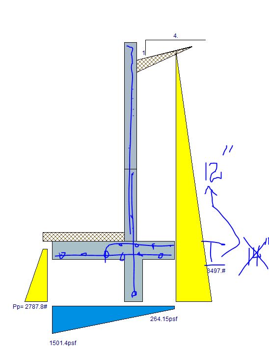
here is a scratch detail. i swear ive seen the vertical bar hooks bend a mere hook length into the footing on countless details, i fail to see why the development cant also be straight, the load is transferred and footing rebar takes the load after that? the question arises when you have the "new" ibc lateral requirement 1807.2.1 loading and then throw in 1/3 PGA for good measure, the loading gets very cumbersome, so the wall needs a big key for sliding...big enough to need reinforcing itself. again this saves almost 20% on the footing thickness. I also cant imagine why running all streaight bars for the entire wall wouldnt be eaiser than doing the bends. (aside: is anybody a fan of reducing hook embed length by stress ratio? im not) (aside #2: really??, 1/3 pga is .33 for onome kenabi method, HUGE...show me a time where a "low" less than 15 feet retainnig wall has failed because of earthquake).
 
Capture_epk6rt.jpg
 
good gawd.... thread507-401855 i will never get that half hour back..... nevermind! i think that once you get your tension into the footing with the vertical rebar by hook or crook (ha pun.....like into the key even?), well then arent you essentially done with that force at least from a design perspective,its not pullin out and it will attempt to "lift" the footing at your design load?? and if it does, then now its the job of the footing/toe reinforment to work after that.
 
Although the odd bend is nice; For small bars, I've seen them made in the field, in a pinch, using a bumper tow ball attachment. If the bar can be propely developed, straight bars will do... bars may have to be smaller diameter which may be problematic for large moments. and don't forget the drains.

Rather than think climate change and the corona virus as science, think of it as the wrath of God. Feel any better?

-Dik
 

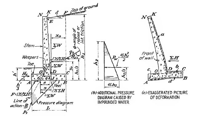
Could be an option for shallow ht retaining walls. If the wall ht greater than 10 ft, IMO, the main bars shall follow the deflected shape . That is, the tension bar at the stem, shall go and extend to toe bottom with a bend . The heel top rebar go straight. The shear key rebar should be addet as separate simple form. Another point, the key should be provided to mobilize the base friction only so , with limited width and ht, limited rebar demand.

The following picture is a snap from a very old book ( FOUNDATIONS OF STRUCTURES by DUNHAM , 1950)
retaining_wall_ysq2tw.jpg


IMO, no need to reinvent the wheel again..

The following doc. is from CALTRANS ( free to download ) which explains the use of shear key for retaining walls..

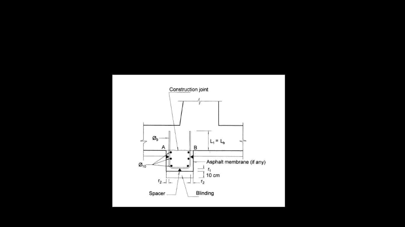
And the following rebar detail from (MANUAL FOR DETAILING RC J.CALAVERA)

Shear_nib_pa1awa.jpg


Mater: you appear to be designing a concrete sheet pile wall more than a T-wall. The load transfer from wall into the footing is not clean nor robust. I do not recommend this approach. HTURKAK's suggestion to "follow the deflected shape" is sound, and in general a good approach for reinforcing design.
Secondarily, I would avoid deep keys. Ideally keys are shallow "shear" keys (less than 3 ft, nor more than half the footing heel), not flexural keys. Deep key behavior is not well established / accepted in the industry.
 
appreciate the responses....the footing would have #5@12" EW @ btm of the footing the entire length. lets put it to bed, but as my last word in.. the development into the key might as well be an actual plate welded onto the bottom of the rebar and extended to udnerneath the footing, why isnt that a gauaranteed load path to get the load it into the footing (same as a vertical bar developed into the key?


OK, so that particular detail is "not robust" from many comments, but doing a hook of 18" or so is? since no details that i have ever seen (red flag) has what was proposed.... i will design a "normal wall" stem vertical bar matching the footing reinforcement to continue all the way into end of toe. with regards to key design and general design, has anyone been tasked with providing the "recommended" .3H groundwater allowance, adn THEN try to get a seismic load allowantce as "required" for walls 6-12 foot high on top of that with a SDS of 1.98? And if so, can you THEN tell me my key is too deep? [bigglasses]

details to follow
 
For us, it's a rare occasion where we add a shear key. When we do, we still need reinforcement in the bottom of the toe, so hooking the stem reinforcement and extending it into the toe is generally still the most efficient way to reinforce the wall. Bending is not a major cost factor for rebar. Placing it and maintaining that placement, i.e. having something to tie the bars to that will keep them in place, is one of the things that keeps the costs down.

Also, using less steel, and having fewer bars to place, lowers costs. For bridge decks, typically half the transverse reinforcement is 'crank bars' that are in the top of the slab over the girders and in the bottom of the slab between the girders, so they have 4 bends per girder; on a 6 girder bridge, that 2 dozen bends in each bar, and sometimes hundreds of bars. Comparing to bridges that have a top and bottom straight bar in place of the crank bars, the cranks are the more cost-effective option by a good margin..

Rod Smith, P.E., The artist formerly known as HotRod10
 
This is from the CRSI Design Handbook:

Screenshot_2021-03-29_133448_rwasjl.png


I actually used a similar detail (extending the shear key vertical bar into the wall) on a project that is currently halfway through design. For what it's worth, the contractor has reviewed the detail and said he loves it. Maybe because it gives them something to tie the wall bars to.
 
I can't believe that you guys had this conversation BEHIND MY BACK! Someone should have emailed me... and you know who you are.

OP said:
i think that once you get your tension into the footing with the vertical rebar by hook or crook (ha pun.....like into the key even?), well then arent you essentially done with that force at least from a design perspective,its not pullin out and it will attempt to "lift" the footing at your design load??

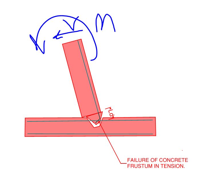
The error in that logic is failing to recognize the difference between rebar development and rebar anchorage. Development is a component of anchorage in most cases but, on its own, does not guarantee that the bars will not pull out of the concrete. And, even if it did, that's relying on concrete in tension for your primary load path which few engineers would be comfortable with in a situation such as this.

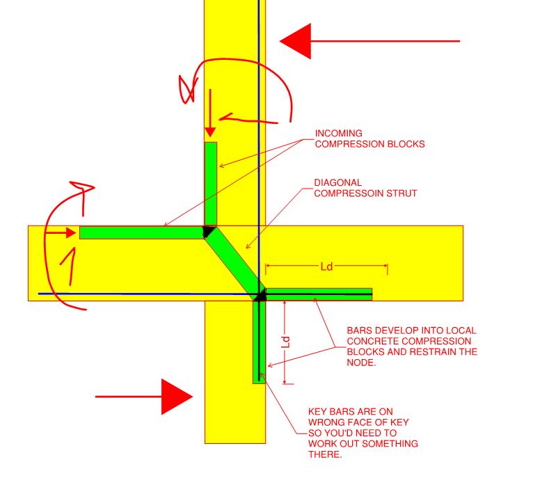
That said, I agree with you that your proposed detailing makes for an excellent moment connection. One of the best in my opinion. It just needs to be conceptualized in a robust manner as shown below. That leaves a few practical problems:

1) Constructability as mentioned by my colleagues above.

2) As shown, the rebar is in the wrong face of the key.

3) Whether or not this arrangement actually reduces your footing thickness is something that would shake out of a strut and tie analysis of the joint.

If architects would let me to this at roof level beam to column joints, I would be thrilled.

c01_xar3ig.jpg
 
You could solve the problem of the straight bars out of the stem being in the wrong face of the key by moving the key back so that they're aligned in the front face of the key. However, then you're back to the issue of needing to reinforce the bottom of the toe another way, and the issue with keeping the vertical bars vertical is back in play.

Rod Smith, P.E., The artist formerly known as HotRod10
 
Kootk said :

The error in that logic is failing to recognize the difference between rebar development and rebar anchorage. Development is a component of anchorage in most cases but, on its own, does not guarantee that the bars will not pull out of the concrete. And, even if it did, that's relying on concrete in tension for your primary load path which few engineers would be comfortable with in a situation such as this.

ok but isnt that what we are doing with our primary load path up in the stem all day every day? resistinig the moment primary load path with rebar tension? (what about my analogy of a welded plate to the rebar and under the footing for the "development,achorage" - impossible for it to fail in tension unless bar blew out.....would that not work either?? impossible!!!!

That said, I agree with you that your proposed detailing makes for an excellent moment connection. One of the best in my opinion. It just needs to be conceptualized in a robust manner as shown below. That leaves a few practical problems:
"One of the best in my opinion." isnt this somewhat typical?
1) Constructability as mentioned by my colleagues above.

please discuss. keys directly underneath and same thickness of wall are always preferred then?, but are they that common?

2) As shown, the rebar is in the wrong face of the key.
( my detail shows the key offest to line up with front of wall, and rebar in the center of the key.... is that really more of a constructability problem then aligned with back? please discuss the formwork issues in relation to the key placement and width.

3) Whether or not this arrangement actually reduces your footing thickness is something that would shake out of a strut and tie analysis of the joint.
only reduces the footing thickiness because you dont need to increase the footing to get the required bend from the verticals into the footing (2 inches less required thickness usually, unless everyone is always comfortable "reducing hook embed by stress ratio" option)

If architects would let me to this at roof level beam to column joints, I would be thrilled.
 
Materofact said:
ok but isnt that what we are doing with our primary load path up in the stem all day every day? resistinig the moment primary load path with rebar tension?

No, not at all. Note that I said that we avoid using concrete in tension. Obviously we do all use rebar in tension. If the stem rebar tension is not either passed around the corner as rebar tension, or truly anchored (as opposed to developed), then one is relying on concrete in tension to prevent the rebar ripping out of the concrete and taking a chunk of concrete along with it. See the sketch below.

Materofact said:
"One of the best in my opinion." isnt this somewhat typical?

No, not in my opinion. Most moment connections take the moment "around the corner" in some fashion as rebar tension. Exterior CIP beam to column moment connections below the roof level do implicitly kind of function kind of like the mechanism that you've proposed which is why they have some prescriptive limits on their proportioning.

Materofact said:
please discuss. keys directly underneath and same thickness of wall are always preferred then?, but are they that common?

See the first post by hokie66 as he has already discussed the constructability issue exactly as I would. Different contractors tend to prefer different things, of course, so it's often difficult to say with 100% certainty what will be preferred in any particular situation.

Materofact said:
..my detail shows the key offest to line up with front of wall, and rebar in the center of the key.... is that really more of a constructability problem then aligned with back? please discuss the formwork issues in relation to the key placement and width

I never said that it was a constructability issue. I said that, as shown in my sketch, the rebar would be in the flexural compression face of the key which is clearly not correct from the perspective of the flexural capacity of the key.

Materofact said:
2 inches less required thickness usually, unless everyone is always comfortable "reducing hook embed by stress ratio" option

The point that I was trying to make is that it is impossible to know if the footing will be 2" thinner unless one has actually done the strut and tie design of the joint to find out if that is workable. Since development does not equal anchorage, it is incorrect to assume that, just because you can develop the bars, you've got your footing depth sorted.

C01_d1cqvy.jpg
 
Status
Not open for further replies.

Part and Inventory Search

Sponsor