Continue to Site

Eng-Tips is the largest engineering community on the Internet

Intelligent Work Forums for Engineering Professionals

  • Congratulations waross on being selected by the Eng-Tips community for having the most helpful posts in the forums last week. Way to Go!

Retaining Wall - Flexural Reinforcement from Stem Into Footing 21

Status
Not open for further replies.

CWEngineer

Civil/Environmental
Jul 3, 2002
269
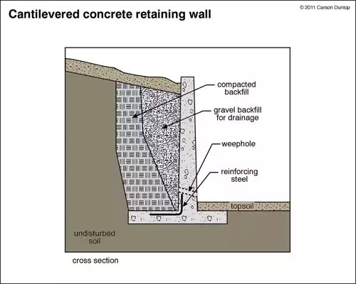
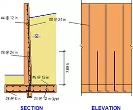
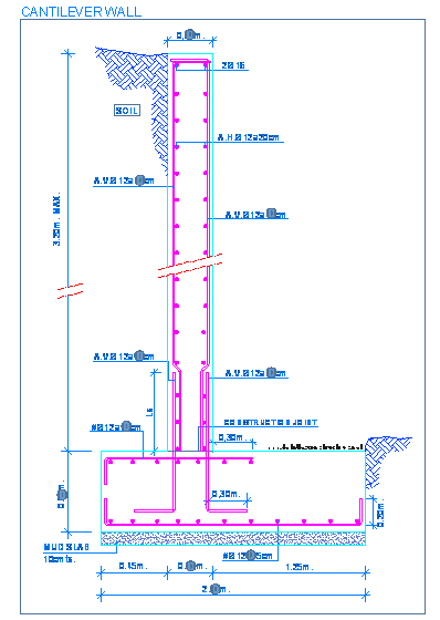
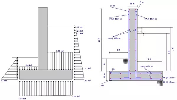
I am trying to get some clarification regarding the flexural reinforcement of the stem of a retaining wall into the footing.

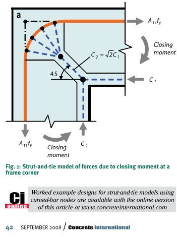
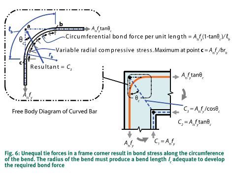
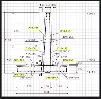
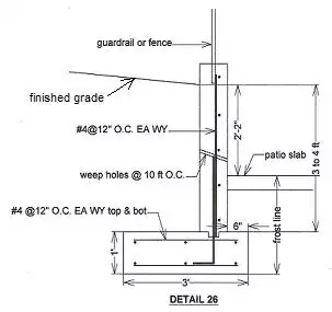
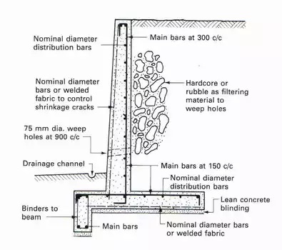
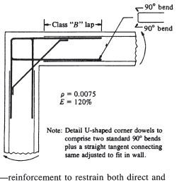
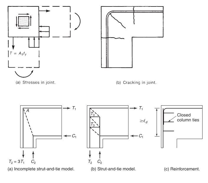
Does the flexural reinforcement in the stem of a wall, need to be developed into the toe, such as show in Figure 1 of the attached document. Or is providing a standard hook (12db), sufficient, such as that show on Figure 2 of the attached document? If providing a standard hook is sufficient, can the hook be turned towards the heel?

Thanks in advance
 
 http://files.engineering.com/getfile.aspx?folder=8fc7a958-bb23-4694-a010-30dca047d4a9&file=Flexural_Reinforcement.pdf
Replies continue below

Recommended for you

Some teasers that will encourage forum members to run out and purchase this fine document on curved bar nodes:

Capture1_y9lwri.jpg

Capture2_v8pz7m.jpg

Capture3_jgrgfu.jpg

Capture4_q7vtcc.jpg


I like to debate structural engineering theory -- a lot. If I challenge you on something, know that I'm doing so because I respect your opinion enough to either change it or adopt it.
 
Arthur Nilson is my go to guy for corner and tee joints in concrete structures.
 
previous discussion on hooks

access to an old version of BS8110 - equation 50 is on page 83

To get back on track - OP question - Does the reinforcement have to be developed into the toe? No, it just has to be developed into the footing and into the wall. Will a standard hook work? Yes as long as it is embedded Ldh into the footing. Can the hook be turned toward the heel? Yes, but it is bad practice (zero toe walls have been built).

If you'd like to design to British standards, then don't use terms like "Standard Hooks." If you'd like to save a couple of inches on that footing depth and you are itching to publish an engineering dissertation on curved-bar nodes as well as field an extra RFI from the rebar detailer, go ahead with strut and tie modeling.
 
Forgetting about code rules and logic etc and looking at where tension reinforcement needs to be, we need tension reinforcement down the back face of the wall and in the bottom of the toe and the top of the heel.

I would have top and bottom reinforcement in the footing to provide the last 2 of these. The bars in the back face of the wall then need to develop past the top footing bars and also lap to the bottom footing bars in the toe with sufficient bend diameter to allow force to develop fully past the bend to form the lap with the bottom bars. The horizontal length of the wall bars needs to be in the same layer as the footing bars and below the support footing bars so as to not create a zone where concrete u=is being relied on to take the tension..
 
Teguci,

If you have a zero toe wall, you have an opening corner joint. Your statement that "a standard hook will work" is incorrect if the joint is to take the full moment. You need to study the details which KootK posted, which list the efficiencies of various types of joint reinforcement. Testing by Nilsson and others has shown that the double hairpins as shown in Figure 13-29 are really the only way of fully developing opening corner joints.
 
As I have presented methods that seem to be controversial, I thought I might expand a bit upon what I actually do in practice:

1) I don't use eurocode provisions except as an aid to my own understanding.

2) I use the CRSI joint detailing whenever possible (95% of the time) and don't bother with curved bar node STM theory in those instances except as an aid to my own understanding of joint behaviour.

3) When I have cause to stray from the CRSI detail, I use a spreadsheet that a colleague made at my request to investigate the joint using the joint using the curved bar node STM model. It's rudimentary and requires some manual parameter iteration. Maybe twenty minutes per run to set up and fiddle with.

4) When I use strut and tie models -- for retaining walls or anything else -- my goal is never to shave down material quantities. This is partly because, in my experience, STM never does reduce quantities. Rather, it adds to them. The goal with STM, at least for me, is to make my designs safer, not cheaper.

As an experiment, I googled images for "retaining wall reinforcement". About a third of what comes up demonstrates a fundamental lack of concrete joint detailing principles in my opinion. It's a problem.

image_mbgowo.jpg

image_ggxbrd.gif

image_kesxyh.jpg

image_f6pbfb.jpg

image_mmzmog.jpg

image_wzqqyk.jpg

image_owdob2.jpg

image_ltgczt.png

image_gcudyj.jpg


I like to debate structural engineering theory -- a lot. If I challenge you on something, know that I'm doing so because I respect your opinion enough to either change it or adopt it.
 
Figure 13-27 above has enlightened me. I have always followed the CRSI details, except I have typically omitted that diagonal bar. I felt if the bar from the stem wall into the footing is developed in both directions (above and below the construction joint), and the bars in the footing are developed on both sides of the stem wall, then there is no chance of failure.

I think I will start including the diagonal bar in my retaining wall designs.

Out of curiosity--is the problem with Figure 13-27 a strength problem (reduced capacity), or a serviceability problem (joint opens up)?

DaveAtkins
 
I too will have to consider adding the diagonal bar in 13-27. We have used that detail in watertight structures like one of the figures above, but it is not something we tend to add in a retaining wall application.
 
- further reading on the history of ACI standard hooks as well as new testing regarding their effectiveness at different angles (ex towards the toe or towards the heel)

So again, back to the OP, yes a standard hook developed into the footing will provide full tension development of the stem wall reinforcement. This standard hook at the development length has been tested to its yielding capacity, has been codified by ACI, and has withstood years of real world scrutiny. Pardon our North American misconception.

Please mind that I am not talking about compression failures in the footing or proper footing reinforcement. That was not your question, but I do argue that increasing the depth of the footing for Ldh will have a positive impact on those issues. Further thoughts - Do we provide a full vertical lap splice for the hooked end of haunch/corbel reinforcement? How about for moment connections at beam to columns? Edge beams, pile to pile caps, etc...
 
Yes indeed, interesting and illuminating thread.

Koot, those images you found are awful, the stuff nightmares are made of, frankly. I wish I could say I haven't seen drawings with the likes of such, but I have.

Regarding Fig. 13 (a), the plan view of the walls, I can't imagine anyone designing corner reinforcing that way, save for my previous sentence. I can easily imagine them getting built any of those - or other - ways, though. Which leads to my next question...

Regarding the diagonal bar in Fig. 13 (b) has anyone found them to cause difficulties with placement or consolidation? If so, I can see how on a large project the issue could be addressed but I can also see how on a small project they might get intentionally omitted at the site.
 
Dave Atkins said:
Out of curiosity--is the problem with Figure 13-27 a strength problem (reduced capacity), or a serviceability problem (joint opens up)?

It's definitely a strength problem as the efficiency percentages quoted indicate [Moment capacity achieved in testing / Moment capacity calculated by conventional procedures * 100]. The crack widths quoted are, I believe, the values estimated to accompany a serviceability load level (55% Mn for example as indicated). At serviceability crack widths of 1/4", it's pretty tempting to call that a failure as well from the perspective of corrosion and water tightness (where required).

Sadly, I do not yet have Nilsson source document (Link). Might have to rectify that. If you google the document title however, you'll come up with plenty of derivative papers:

[link file:///C:/Users/apearson/Downloads/effectofcornerangleonefficiencyofreinforcedconcretejointsunderopeningbendingmoments-141103153331-conversion-gate02.pdf]Link[/url]
Link
Link

I've known engineers who compensated for the efficiency percentages by simply adding that much more rebar. I'm skeptical of that approach, however, as I'm not convinced that it's a linear thing.

Capture1_essb1t.jpg


I like to debate structural engineering theory -- a lot. If I challenge you on something, know that I'm doing so because I respect your opinion enough to either change it or adopt it.
 
Dave said:
Regarding the diagonal bar in Fig. 13 (b) has anyone found them to cause difficulties with placement or consolidation

I'm assuming that we're talking about the wall corner detail below. I've only attempted it in large scale industrial applications where there was plenty of room and there were no complaints. I would wouldn't be pitching it in your standard 8" stem wall or anything like that.

Capture1_lbpjfe.jpg


I like to debate structural engineering theory -- a lot. If I challenge you on something, know that I'm doing so because I respect your opinion enough to either change it or adopt it.
 
Actually I was thinking to their use at the base of the stem of a cantilever retaining wall. With vertical concrete placements sometimes diagonal bars can case problems. I'm wondering if anyone here has dealt with that in this circumstance. I agree that (per the studies) they sound like they're what's required to control cracking at that joint. However, if it proves to be too difficult to build it will get left out more often than not.
 
teguci said:
Do we provide a full vertical lap splice for the hooked end of haunch/corbel reinforcement?

I do in fact. Obviously, though, I realize that there are older, empirical methods (ACI shear friction etc) that do not require this. Strictly speaking, if you approach it from a strut and tie perspective, it's tough to avoid the need as you wind up with another of those situations where you need to transfer rebar tension force around a bar bend. The sketches below are taken from the curved bar node article that I posted above and MaGregor's text.

teguci said:
How about for moment connections at beam to columns?

Absolutely at roof level edge columns. We don't typically bother at other conditions where there is beneficial clamping action available from columns both above and below. That said, I'm sure that these connections deserve more attention than they typically receive. And in seismic country, they get it. The sketch below is taken from MacGregor and illustrates the demand.

teguci said:
Edge beams, pile to pile caps, etc...

Oftentimes yes. I'd need more information on the specifics to respond in any meaningful way however.

Capture_xwiwsz.jpg
20151009_Chickens_x9ulzr.jpg


Capture1_r9q640.jpg


I like to debate structural engineering theory -- a lot. If I challenge you on something, know that I'm doing so because I respect your opinion enough to either change it or adopt it.
 
Dave said:
Actually I was thinking to their use at the base of the stem of a cantilever retaining wall.

I never get push back from commercial / institutional builders and quality seems to be fine. Residential guys tend to complain about it so, since these are usually pretty small walls, I just over design the connection and don't bother with the diagonals. Once nice feature of the STM method is that it demonstrates sufficient strength, if not crack control, without the use of the diagonal bars.

To be honest, the biggest problem with the diagonal bars is when my competitors don't include them and make me look bad. Damn competitors.

I like to debate structural engineering theory -- a lot. If I challenge you on something, know that I'm doing so because I respect your opinion enough to either change it or adopt it.
 
>>>I never get push back from commercial / institutional builders and quality seems to be fine.<<<

Hmm, ok, no reason not to call for them then, I suppose. Good to know. Thanks.
 
Teguci,

I do change my mind, but haven't in this instance. In the thread you referenced, see my comments about Nilsson's work with opening corner joints.
 
This is the same concept as a ground floor slab supported by a basement wall below - to count on continuity/slab neg moment you don't just have std hooks each way. We show very outside face wall bars that bend down and extend a full tension lap into the slab. Same deal.
 
Hokie,
Do you know if CRSI corrected the Ldh requirement?
 
Status
Not open for further replies.

Part and Inventory Search

Sponsor