Continue to Site

Eng-Tips is the largest engineering community on the Internet

Intelligent Work Forums for Engineering Professionals

  • Congratulations KootK on being selected by the Eng-Tips community for having the most helpful posts in the forums last week. Way to Go!

Retrofit Steel Beam - How much of the Span? 1

Status
Not open for further replies.

jlleiber

Structural
Oct 6, 2016
18
I am looking at finishing out my basement and have a W8 beam that is supported by the exterior concrete wall and (2) pipe columns. The total beam length is only 15', so I'm trying to remove the center pipe column. From a moment and shear strength standpoint, the W8 is still good, but deflection is killing it. I can't sacrifice a ton of headroom, so my first thought is to weld a 6x2 tube steel to the bottom flange. This more than doubles my moment of inertia and gets me to an acceptable deflection.

My main question is: if my concern is the max deflection at midpoint, how much of the 15' span do I need to have the 6x2 tube steel added? My first thought is 2.5' in from each end for a total retrofitted length of 10', but how should I verify this?

Anything else to consider? Other ideas?
 
Replies continue below

Recommended for you

Model and analyze the beam with multiple section properties along its length that match the upgraded sections. Calculating this by hand would be tough so an analysis model in a program would be what I would do.


Check out Eng-Tips Forum's Policies here:
faq731-376
 
Unless you have a way to remove the existing dead load on the beam, your tube steel reinforcement will only be engaged for live load deflection. Keep that in mind.
 
JAE - that's what I was thinking. It should be easy to set up an excel sheet to calculate the deflection, given "x" along the span. what I'm getting a little stuck on is this: I check the deflection at midpoint and say it's 1/4". Then I calculate the deflection of the beam just where the reinforcement stops and let's say I fine tune the tube steel length so the deflection here calcs out to be 1/4" also. What does the actual deflection curve look like? Would the design deflection just be whichever section sees the most deflection? I'm trying to do it by hand as I don't have an alaysis program to model this up with

Lex - for constructability, I think the only way I can do this is temporarily support the joists on either side, remove the center post, install the tube steel. That should let the tube steel engage for everything, right?
 
If you want to do it with excel it'll be conjugate beam with 3 parts:
part 1: I,w8 alone
part 2: I,w8+hss
part 3: I,w8 alone

The HSS will need to extend beyond the part 1-2 and part 2-3 interface long enough for a weld to develop the Mu,max*Q,hss/I,w8+hss

Also check out this site:
Open Source Structural Applications:
 
I'm not sure I'm following you on your spreadsheet approach.

Assuming you will shore up the floors and add the tube to a relatively unloaded beam, the new beam configuration will have different stiffnesses along the length of the beam.
You could perhaps do a moment area analysis of the simple span to arrive at the deflections. The two sections work together so your phrase "whichever section sees the most deflection" doesn't make sense - the sections both are attached and see the same deflection at each point along the span, right?


Check out Eng-Tips Forum's Policies here:
faq731-376
 
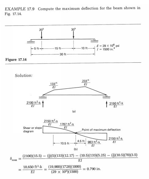
Here's a Moment Area example for a simple span beam. In your case you'd probably have simply a uniform load:
Moment_Area_1_hyyl8k.jpg


Check out Eng-Tips Forum's Policies here:
faq731-376
 
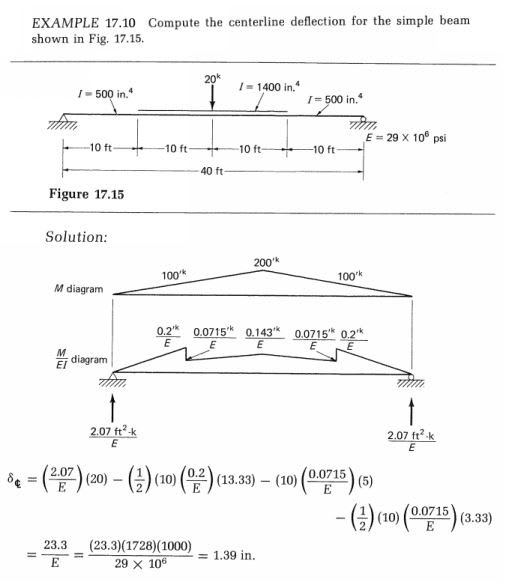
And here's one where they've added some strengthening to the partial span (like what you are doing):

Moment_Area_2_gvcs0s.jpg


Check out Eng-Tips Forum's Policies here:
faq731-376
 
Ahh, right. That's exactly what I need. Thanks, JAE.

And thanks for those links, Celt. Great information.
 
I assume since you're intending to decrease your headroom by 2", that it's the deflection of the floor joists above that would be unacceptable. That being the case, if the strength is adequate, why not just shim the floor joists as necessary to make up for the extra deflection?
 
E720 - my old structural analysis textbook. I can get you the title tomorrow if you want it.

Check out Eng-Tips Forum's Policies here:
faq731-376
 
HotRod - the joists are nailed to a nailer board which is fixed to the top of the steel beam and allows me to consider the compression flange braced. Additionally, this is in our kitchen/dining area and we've had 25-30 people in here at one time. So, even with the shims under the floor joists, the whole floor would deflect under this live load and start buckle the floor or messing with my cabinets I would think
 
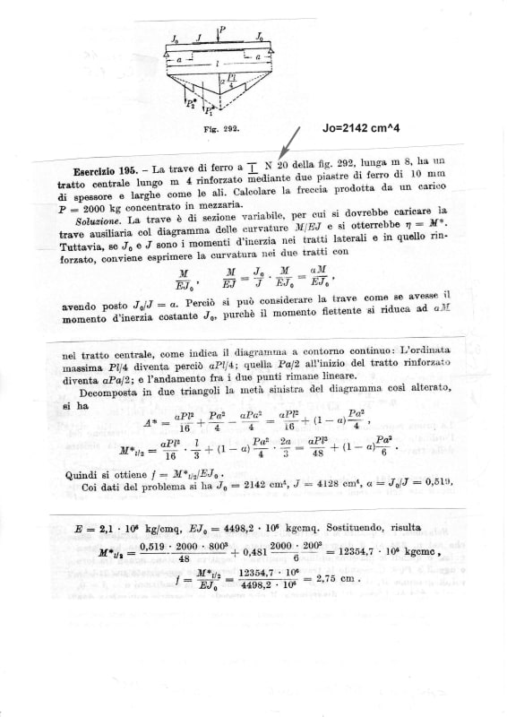
general calculation (ready to help in translation, if needed)

beam_retrofit_aowsab.jpg
 
I saw your post stated "Anything else to consider? Other ideas?". So here are some things to consider.

1. I think there are several free 2-dimensional structural programs available. I recall at one time RISA 2D was free.

2. It seems you are getting most of your increased Ix from the Ad^2 part of the formula. The Iy can't be that much for a 6x2 tube turned flat. I am assuming you are turning it flat. For that reason, I would use a flat plate of whatever thickness I needed to keep as much headroom as I could.

3. As several people point out, you will most likely have to support (and slightly lift) the current dead load and live load in order to install the reinforcing. In doing that, be sure not to use the allowed bending formula F1-8 in the old ASD method since it is not applicable when the tension flange has less area than the compression flange. I am sure the LRFD method has a similar requirement.

4. Meeting a code requirement is one thing, messing with an existing and older structure is another. I assume right now, the exact location of the column to be removed has about zero sag. When you remove the column, it will then have possibly the maximum sag. That will affect everything above it even if it is within code. Cabinets, windows and doors are generally installed level regardless of how level or unlevel the floor below them is. If the floor then sags a 1/4" upon column removal and if any of the items are above it, they may sag unevenly. A door can sag a mile and still close, as long as both sides sag the mile. If one side sags 3/16" more (or less) than a mile, the door will stick since there is generally about an 1/8" gap in a door. This is just something to bear in mind.

5. I saw you mention cabinets. If there are kitchen cabinets on a wall above this beam, you need to use more than a design floor live load in psf. Cabinets full of can goods or dishes weigh a lot. I generally treated as line loads in addition to the floor live load.
 
Vibration might also require a look to ensure you are not creating an issue, though if there are full height walls there's plenty of damping and structure for the beam to hang up on so you won't see the design deflection in all likelihood. Doubling the span and only doubling the moment of inertia over only part of the span would increase overall deflection by much more than a factor of 2 for example.
 
jlleiber said:
"HotRod - the joists are nailed to a nailer board which is fixed to the top of the steel beam"

Ok, so you can loosen the connections between the nailer and the beam and shim there.

Just increasing the moment of inertia of the beam will decrease the amount of new deflection, but it won't mitigate it.

To decrease deflection due to people moving around, Ron247 is right, you can get the same increase in I from a plate of slightly more area than the tube, without losing as much headroom. Plate is also cheaper and more readily available than tube sections.

After consideration of all the loading, if the strength is sufficient, you could start by shimming to restore the floor to its original level. Then you can see how it feels walking on it or when you have a party, and add the plate or tube to the beam if you find the LL deflection to be objectionable. You may find it isn't as bad as you think it will be.
 
Great point about using the plate instead of a the tube steel. I can get a 3 in^2 area by using a 1/2"x6" plate and that gets close to the area of the tube steel I want to use and the Ad^2 aspect is where I'm getting most of my increased moment of inertia.

In terms of where the beam is, there are no cabinets directly above, only flooring. My main concern would be what the cabinets that are resting in the middle of the floor joists will do if the beam delfects a 1/4". The main load on the floor joists comes from a 48"x96" island (with cabinets) in the middle of the span of the floor joists.

I also understand that the beam over post is currently at 0" sag and adding reinforcement will not mitigate all the deflection, so maybe I'll just go overboard on the reinforcing to limit the sag with 40 psf LL to 1/8". For starers, 25 people will translate to maybe 20-25 psf and I can't imagine ever getting a full 40 psf load.

And to HotRods point, I could install the reinforcing on the beam and release the load back onto the beam (current cabinetry, dishes etc) and then shim out the deflection caused by the permanent DL from the cabinets, dishes, etc
 
Status
Not open for further replies.

Part and Inventory Search

Sponsor