As extension of the profis discussion in my other thread.
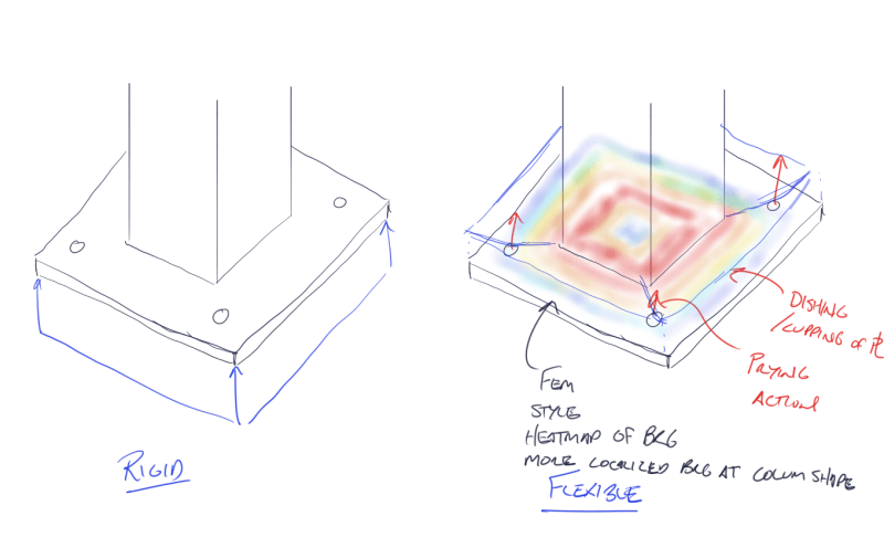
When performing a rigid plate analysis:
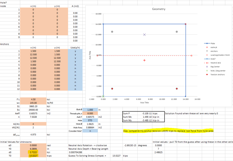
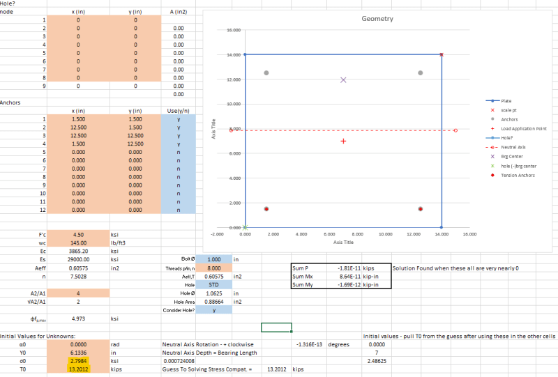
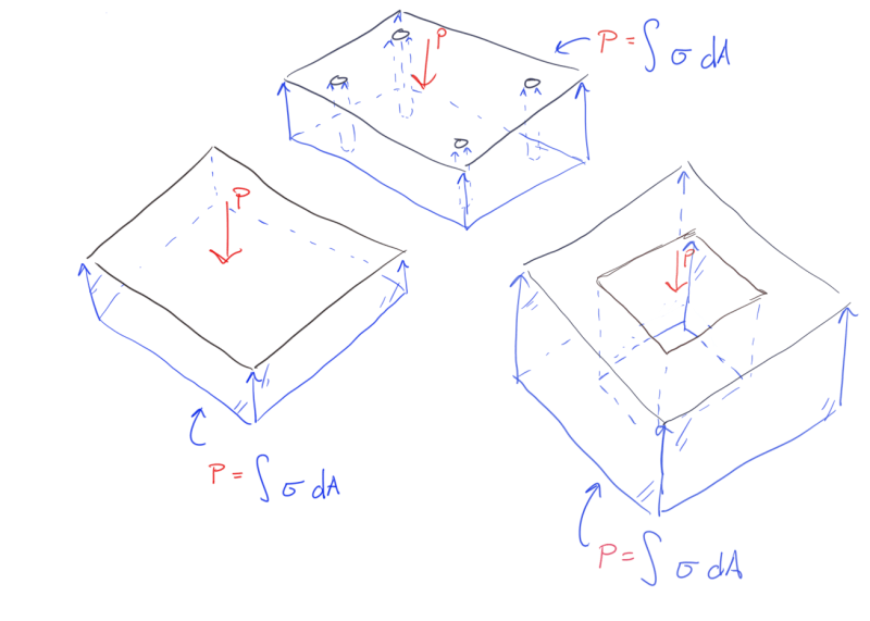
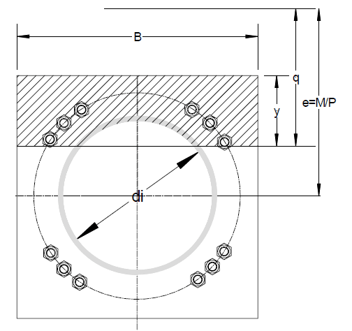
1. Should the bolt holes on the compression side of the plate be considered as reducing the available area for compression resistance, both Design Guide 1 and Blodgett don't take the holes into account?
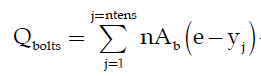
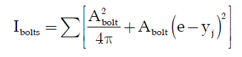
2. If not accounting for the holes then shouldn't the anchors on the compression side of the plate be designed for a minimum tension of the concrete stress x the hole area so that missing resultant force is accounted for?
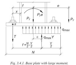
3. How are folks back checking the rigid plate assumption, or rather how was this checked before tools like RISA Base and the new CBFEM checking in Profis? Based on some limited research I get the feeling this usually doesn't get a whole lot of attention and the plate is designed against yield stress + phi/omega factor and assumed this makes it stiff enough.
My Personal Open Source Structural Applications:
Open Source Structural GitHub Group:
When performing a rigid plate analysis:
1. Should the bolt holes on the compression side of the plate be considered as reducing the available area for compression resistance, both Design Guide 1 and Blodgett don't take the holes into account?
2. If not accounting for the holes then shouldn't the anchors on the compression side of the plate be designed for a minimum tension of the concrete stress x the hole area so that missing resultant force is accounted for?
3. How are folks back checking the rigid plate assumption, or rather how was this checked before tools like RISA Base and the new CBFEM checking in Profis? Based on some limited research I get the feeling this usually doesn't get a whole lot of attention and the plate is designed against yield stress + phi/omega factor and assumed this makes it stiff enough.
My Personal Open Source Structural Applications:
Open Source Structural GitHub Group: