Hi All,
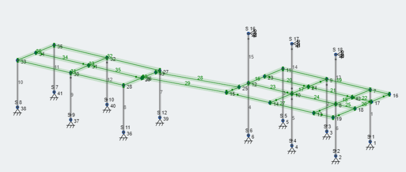
Looking for some opinions on the design below. It’s an outdoor patio which is only connected to the adjacent structure at the top of the three columns in the right side of the picture below (supporting overhanging roof structure). For scale, the platform consisting of wide flange beams (shown in green) are only 8’ above grade. Loading is as follows:
1. Live load 1.92 kPa
2. Snow load 2.2 kPa ULS
3. Dead load 0.4 kPa (composite decking with 2x8 framing on 16” centers between packed beams).
4. Additional dead loads: Hot tub (5400 lbs) between nodes 35,32,30, and 33 (left most bay). 5” concrete slab between nodes 11,7,8, and 12 (structure on right which is beneath overhung roof).
5. Wind loading: I’m applying wind loads assuming the structure could be enclosed. 0.26kPa SLS and 0.43 kPA ULS.
6. Low seismic area (Ontario, Canada).

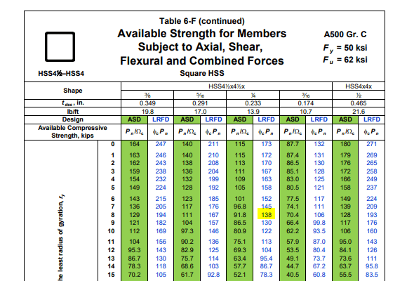
Fabricator is proposing 4x4x1/4” HSS columns with W8x15 beams for the floor. For lateral stability, I have modeled the corner nodes at the columns as fully restrained moment connections. Here are my concerns:
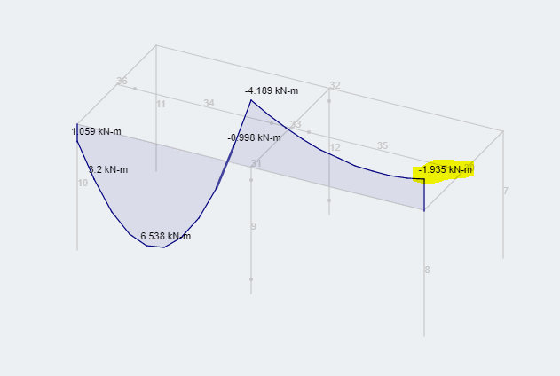
1. Very little moment is being transferred from the beams to the columns due to the relative stiffness of the two members. With the lateral loads being relatively low, my SLS lateral deflections are still meeting criteria though (h/500 for wind and h*0.025 for seismic). Is it necessary to consider a stiffer column in that case?
2. I have modeled continuous beams ( node 11 to 15, node 9 to 14, node 7 to 13) that cantilever beyond the columns in the structure on the right (members 16,17, and 18). It’s my understanding that the deflection limits for a cantilever are 2*Cantilever length/360 for live load and 2*Cantilever length/240 for unfactored dead + live load (equates to 15mm). Considering pin ended members 28 and 29 span these two structures and are supported at the end of the cantilever, could this walkway seem a bit too lively under load?
All comments are greatly appreciated. Thanks in advance!
Looking for some opinions on the design below. It’s an outdoor patio which is only connected to the adjacent structure at the top of the three columns in the right side of the picture below (supporting overhanging roof structure). For scale, the platform consisting of wide flange beams (shown in green) are only 8’ above grade. Loading is as follows:
1. Live load 1.92 kPa
2. Snow load 2.2 kPa ULS
3. Dead load 0.4 kPa (composite decking with 2x8 framing on 16” centers between packed beams).
4. Additional dead loads: Hot tub (5400 lbs) between nodes 35,32,30, and 33 (left most bay). 5” concrete slab between nodes 11,7,8, and 12 (structure on right which is beneath overhung roof).
5. Wind loading: I’m applying wind loads assuming the structure could be enclosed. 0.26kPa SLS and 0.43 kPA ULS.
6. Low seismic area (Ontario, Canada).

Fabricator is proposing 4x4x1/4” HSS columns with W8x15 beams for the floor. For lateral stability, I have modeled the corner nodes at the columns as fully restrained moment connections. Here are my concerns:
1. Very little moment is being transferred from the beams to the columns due to the relative stiffness of the two members. With the lateral loads being relatively low, my SLS lateral deflections are still meeting criteria though (h/500 for wind and h*0.025 for seismic). Is it necessary to consider a stiffer column in that case?
2. I have modeled continuous beams ( node 11 to 15, node 9 to 14, node 7 to 13) that cantilever beyond the columns in the structure on the right (members 16,17, and 18). It’s my understanding that the deflection limits for a cantilever are 2*Cantilever length/360 for live load and 2*Cantilever length/240 for unfactored dead + live load (equates to 15mm). Considering pin ended members 28 and 29 span these two structures and are supported at the end of the cantilever, could this walkway seem a bit too lively under load?
All comments are greatly appreciated. Thanks in advance!


