Continue to Site

Eng-Tips is the largest engineering community on the Internet

Intelligent Work Forums for Engineering Professionals

  • Congratulations KootK on being selected by the Eng-Tips community for having the most helpful posts in the forums last week. Way to Go!

Rigid Frame Design with Cantilever W beams and HSS Columns 1

Status
Not open for further replies.

Deener

Mechanical
Aug 30, 2018
48
Hi All,
Looking for some opinions on the design below. It’s an outdoor patio which is only connected to the adjacent structure at the top of the three columns in the right side of the picture below (supporting overhanging roof structure). For scale, the platform consisting of wide flange beams (shown in green) are only 8’ above grade. Loading is as follows:
1. Live load 1.92 kPa
2. Snow load 2.2 kPa ULS
3. Dead load 0.4 kPa (composite decking with 2x8 framing on 16” centers between packed beams).
4. Additional dead loads: Hot tub (5400 lbs) between nodes 35,32,30, and 33 (left most bay). 5” concrete slab between nodes 11,7,8, and 12 (structure on right which is beneath overhung roof).
5. Wind loading: I’m applying wind loads assuming the structure could be enclosed. 0.26kPa SLS and 0.43 kPA ULS.
6. Low seismic area (Ontario, Canada).
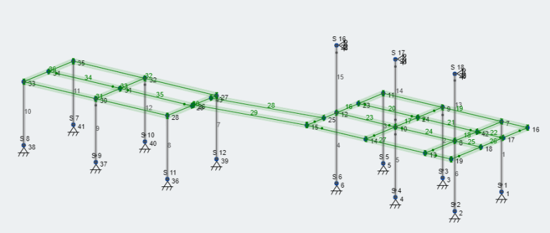
Structure_wzgel6.png


Fabricator is proposing 4x4x1/4” HSS columns with W8x15 beams for the floor. For lateral stability, I have modeled the corner nodes at the columns as fully restrained moment connections. Here are my concerns:
1. Very little moment is being transferred from the beams to the columns due to the relative stiffness of the two members. With the lateral loads being relatively low, my SLS lateral deflections are still meeting criteria though (h/500 for wind and h*0.025 for seismic). Is it necessary to consider a stiffer column in that case?
2. I have modeled continuous beams ( node 11 to 15, node 9 to 14, node 7 to 13) that cantilever beyond the columns in the structure on the right (members 16,17, and 18). It’s my understanding that the deflection limits for a cantilever are 2*Cantilever length/360 for live load and 2*Cantilever length/240 for unfactored dead + live load (equates to 15mm). Considering pin ended members 28 and 29 span these two structures and are supported at the end of the cantilever, could this walkway seem a bit too lively under load?
All comments are greatly appreciated. Thanks in advance!
 
Replies continue below

Recommended for you

My comments:

1) I would be wary of treating the left and right parts of this as one structure, connected by the bridge, for lateral purposes. I'd feel a lot more comfortable ensuring that the structure on each side of the bridge were laterally stable in it's own right. Obviously, those two story columns on the right side will aid stability there in a way that likely will not translate well to the stuff on the left side of the bridge.

2) You may find it challenging to develop a sufficiently strong and stiff moment connection between an HSS4x4 and a W8x15. I'd investigate that carefully before sinking too much time into the macro-design of the scheme.

3) The hot tub makes me nervous for its possible impact on P-delta stability. For something like this, I expect that P-delta will be your dominant stability concern and govern over the relatively minor impacts of wind and low seismicity.
 
KootK, you are the best. Thanks so much for the intelligent comments. I'll address your comments and perhaps spark more points.
1. I completely agree. Although I show beam members 28 and 29 in the picture, I have evaluated both structures as independent. Point loads have been used in place of where the beam members connect into each structure. Each structure has independent stability.
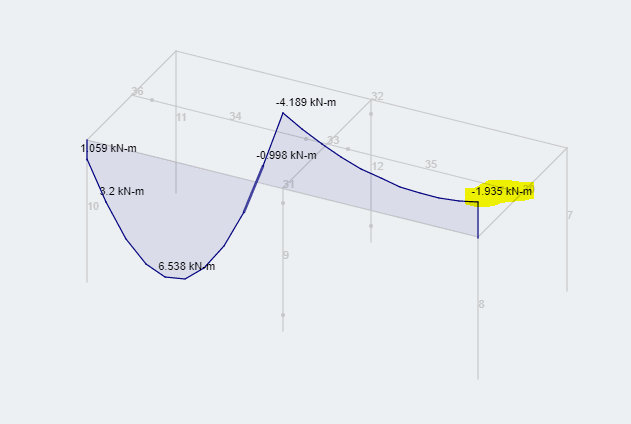
2. My FEM model shows that very little moment is being transferred from the beam into the column (let's say around 3kN*m for worst case scenario). Check out the moment diagram for the beam in the simple structure. You can see the end moments in the beam are quite low. For this reason I am hopeful that I can detail a moment connection to resist this load.
Moment_Diag._ut5w79.png

3. Most excellent point. I'll run a second order analysis with the larger of either the notional loads applied (2% of dead - 900 kN ) or wind/seismic. Seismic is currently giving the largest lateral displacement of 8mm.
Does that all seem reasonable to you?
 
I'm happy to help Deener.

Deener said:
2. My FEM model shows that very little moment is being transferred from the beam into the column (let's say around 3kN*m for worst case scenario)

I would expect the column moments to be low for the gravity only load cases. That, because of the relative stiffness of the beams and columns as you mentioned. It's the moments that would be generated by P-delta effects that I feel are the most critical to your structure.

Deener said:
Does that all seem reasonable to you?

It's difficult for me to tell based on what you're written. To be explicit, here's what I feel needs to happen:

1) Yes, investigate wind and seismic in appropriate combination with wit gravity loads.

2) Also investigate stability considering your full gravity load case in combination with notational lateral loads but no wind or seismic.

For a structure such as yours, with that hotub and beefy 5" concrete deck, it's entirely possible that #2 may be the governing load case.

I see that you're located in Ontario. As a fellow Canuck, I feel comfortable expressing my belief that the Canadian steel standard sucks butt when it comes to stability design. It says the right things in very high lever terms and it permits designers a lot of freedom which some folks value intensely. In my opinion, the Canadian steel standard fall short when it comes to providing clear, actionable advice to designers with regard to how to approach stability problems. We don't all have PhD's in stability after all. In my experience, a significant portion of Canadian structural engineers will fail to recognize that steel moment frames actually require consideration of P-delta effects. I know, that probably sounds unkind of me to say. I call 'em like I see 'em though and give no quarter to my countrymen just because they're my countrymen.

If you want to know your North American stability design forwards and backwards, I would recommend getting your hands on the document shown below.

C01_vhx3oa.jpg
 
Koot,

Since it appears that Deener is using Risa, which is supposed to take into account the P-Delta effects directly, do you feel that if he accurately set up his load combinations to apply the loads indicated in your case 2 that would be enough thought put into the overall stability of his structure?

I do agree that it is a concern in this case since you've essentially got a whole crapload of consistent dead load (water weight plus concrete) sitting on essentially matchsticks. So any lateral movement may cause large P-delta effects in those columns that have minimal ability to resist them.
 
jayrod12 said:
Since it appears that Deener is using Risa, which is supposed to take into account the P-Delta effects directly, do you feel that if he accurately set up his load combinations to apply the loads indicated in your case 2 that would be enough thought put into the overall stability of his structure?

Yeah, I do. But, then, I am of the opinion that one should have a pretty good handle on what their asking their software to do -- and why -- before asking their software to do it. As an example, will RISA automatically divide up the columns into 5+ sub members to work out the P-Baby properly or is that something that the user has to do?

jayrod12 said:
...whole crapload of consistent dead load...sitting on essentially matchsticks

That is precisely my concern and surely a better formulation of it.
 
With respect to RISA, I suppose that my other question is whether or not the software will automatically add notional loads to the max gravity, sans W/EQ load combo. The P-Delta analysis isn't much use if the model lacks a perturbation to get the party started. If RISA has an automated Direct Design Method module that's being used, it may well do this.
 
KootK and Jayrod12 - Thanks for the very useful points. Give me some time to address each of your points so my response is succinct and constructive. In the meantime, let me shed some more light on the situation.
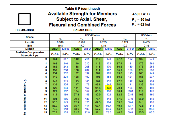
1. The hot tub is on one structure and the 5" concrete slab is on the other. In other words, we have (x4) columns supporting the dead load of the hot tub (5400 lbs), and (x4) columns supporting the dead load of the concrete slab (about 14,000 lbs). Can't argue with the "crapload" designation there. Assuming that's a metric crapload ;). I'll respectfully challenge the matchstick comment, and will be happy to eat my words if proven otherwise. From the AISC table for available compressive strength for HSS4x4x1/4" with an effective length of 8ft, the allowable compressive load is 138 kips. Being simple and dividing the concrete slab weight by 4, each column sees only about 3.5 kip. I understand this doesn't account for second order effects. More to come on that.
Column_Compressive_Strength_dlcbpm.png

2. Not sure if it matters but I'm using cloud software called Skyciv. Each member is evaluated using 9 elements. I need to confirm that this is accounting for P_little delta effects. (P-baby??). As far as I know, I have to apply notional loads manually and also select a second order nonlinear analysis to account for P-big Delta effects.
@KootK - I'm most familiar with the AISC manual of steel construction so I'm happy to hear a fellow canuck reference design guide 28. I find all those guides incredibly useful. Brushing up on the direct analysis method now and potentially running some sanity checks in the Skyciv software. More to come on that.
So much for being succinct...
 
Deener said:
From the AISC table for available compressive strength for HSS4x4x1/4" with an effective length of 8ft, the allowable compressive load is 138 kips.

For pinned based moment frames, keep in mind that your K value is going to in excess of 2.0. So an effective length closer to 24' may well be the order of the day. That said, I'm sure that your posts are probably fine at that value too. For me, it's really more about the stiffness of the connections and their contribution to flexibility.

Frankly, I've seen plenty of mezzanines like this where the "moment connection" is nothing more than a full depth bolted shear tab. And, although I wouldn't do it myself, that often seems to work out.

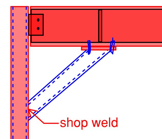
There are very few situations in which I like knee bracing but this is probably one assuming this to be a low ductility frame. Cheap and easy to put together and a nice stiff moment connection.

Deener said:
Each member is evaluated using 9 elements. I need to confirm that this is accounting for P_little delta effects. (P-baby??).

Sounds about right to me.

C01_mupj1u.jpg
 
Correct, Risa does not automatically apply the notional loads and therefore you do need to ensure they are applied in your load combinations appropriately.

The matchstick comment wasn't about the compressive capacity assuming concentric loading. I know a HSS4x4 has boatloads of compressive capacity. However, and I speak from experience here (read: I learned the hard way), that they aren't incredibly stiff laterally.
 
In my mind, my observation that K>>1.0 and jayrod's perception of "matchsticks" are two articulations of the same concept: these are sway columns and that may be a big deal here.

While the structural engineering community seems to largely disdain the K-factor method for frames these days, I actually feel that the alignment charts would be perfect for this. Conceptualized as a bunch of 2D portal each with a stability job to do, the alignment chart method should be accurate, expeditious, and intuitive.
 
Status
Not open for further replies.

Part and Inventory Search

Sponsor