Continue to Site

Eng-Tips is the largest engineering community on the Internet

Intelligent Work Forums for Engineering Professionals

  • Congratulations KootK on being selected by the Eng-Tips community for having the most helpful posts in the forums last week. Way to Go!

Riks in ABAQUS: Is this the forth stopping criteria for Riks?

Status
Not open for further replies.

KyleSong

Civil/Environmental
Sep 18, 2015
28
Hi all friends here:

I am a new researcher and employ ABAQUS to analyse steel bar buckling through Riks algorithm, and concerning the stopping criteria, I want to ask a question. Since when we edit "step", we can specify as much as three stopping criterion: Maximum load proportionality factor, Maximum displacement, and the maximum number of increments. But, since we can also define a displacement along certain direction when we impose displacement control to the model, I want to know whether the displacement I defined is another stopping criteria of Riks? If not, what is the significance of defining a displacement? 

Best Regards,

Kyle

 
Replies continue below

Recommended for you

The defined displacement is just an factor for the arc length. The simulation might show larger displacements, so another stop criteria is useful.
 
Dear Mustaine3:

Thanks so much for reply mine thread! You are so right, I really found the simulation shows larger displacement than the one I defined in the "load module"! You know it is really hard to find another one who is also using the same algorithm, and please help me Mustaine3, I am so urgently need your help, please help me !

I also want to know:

for the loading during the Riks, it is always proportional loading, and follows rules :p(total)=P0(dead load)+ 人(P(ref)-P(0))+, where P(ref) means the load defined in the Riks step, does that mean even if I want to use displacement control, I also need to nominate a load in "load module" to let ABAQUS calculate the P(total) ? If so, what amount of load I should apply? the estimated critical buckling load?

And if I want to use displacement control, is this right: I cannot nominate a displacement at boundary condition, I mean, give a value for one direction in "load module", but can only "control" it at the maximum displacement in "step module"?
Since in normal static analysis we usually add displacement control at boundary condition part, I am not sure whether in Riks is still the same rule.

I will so appreciate your help!!! I have been really frustrated by this tough point, it is killing me :(

Best Regards & thousands thanks with my best sincerity,

Kyle
 
Don't make it more difficult than it is.

The load is the reaction force from the applied displacement. I think there is no need to specify an additional dummy load when you run the analysis displacement controlled.

The displacement is applied the same way as in regular static analysis. So you define a region, a direction and a value. Only the value is not used in the same way. That's why you have different stop criteria.

After the simulation you can plot reaction force vs. displacement from one or multiple nodes of your BC. This is the load-displacement/deflection-curve and you can see the behavior of your structure. Usually the reaction force goes up at the beginning, then down when buckling happens, then maybe up again. Depends on your problem.
 
Thanks very very much for your patient reply, Mr Mustaine3! I feel so luck to get your instructions!

Yes, you are right, I tried as you told me, it is really not necessary to set load for the displacement control process, and when the displacement is imposed to the structure it will produce equivalent Load, so totally necessary to do that, what I silly thought I had..

But, I got another little question concerning the displacement, I know that we can also nominate "maximum displacement of certain point" in "step" module as a stopping criterion, and I want to say, if we want to do the displacement control, we can just give a value in the "step" module to make the calculation stop, but if so, what value we should set for the displacement in "load module", can you give me some clue about this?

Another thing, you told me to plot the reaction force and displacement diagram, and when I try to generate the data from the output files, take displacement as example, it will show me: magnitude, U1 U2 U3, my question is what does magnitude here mean? whose magnitude it is, if the displacement of more than one degree of freedom is non-zero?

Thanks very much!

Sincerely yours,
Kyle
 
But, I got another little question concerning the displacement, I know that we can also nominate "maximum displacement of certain point" in "step" module as a stopping criterion, and I want to say, if we want to do the displacement control, we can just give a value in the "step" module to make the calculation stop, but if so, what value we should set for the displacement in "load module", can you give me some clue about this?

The value of the applied displacement is totally independent of the monitored displacement that can terminate the step. You define the load and this will be applied (and increased) as long as no termination criteria becomes active.


Another thing, you told me to plot the reaction force and displacement diagram, and when I try to generate the data from the output files, take displacement as example, it will show me: magnitude, U1 U2 U3, my question is what does magnitude here mean? whose magnitude it is, if the displacement of more than one degree of freedom is non-zero?

Basic math. An arbitrary vector in 3D has a magnitude (total length) and 3 components in a coordinate system.
 
Dear Mustaine3:

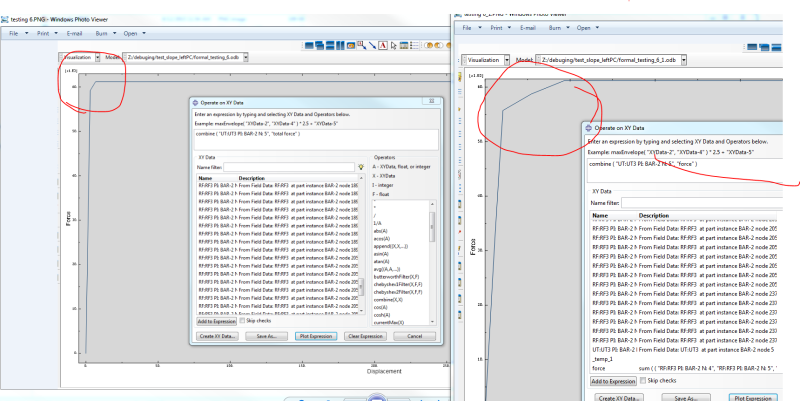
Thanks again for your enlightening answers! yes, I also think the two displacement are totally independent, but if this is the case, when I model the buckling behaviour of a solid bar, what the displacement I should apply to the structure? if load it as load control, I know we can add the yield buckling force to the structure, but for displacement buckling, although it equal to add a corresponding load, but how I can know this corresponding relationship, from the strss-strain relationship of the steel bar? Can you tell me more about how to define a value for displacement control? Since I tried two different value for displacement, and the results just different, and the material property is not changed, but the yield load
11111_wcoo9h.png
in load-displacement diagram varies from one from another, like the picture I attached.

Please help me to explain why this can happen, I mean all the thing are identical, only because of the different displacement input, the results varies, it doesn't make sense, but it happens, Thanks you very much for that! You are a real helper for me, my friend!

Sincerely yours,
Kyle
 
Dear Mr. Mustaine3:

Sorry, Another basic question, can I use Riks to analyse the non-linear bifurcation buckling ?

I have tried so many times, the results are always yield do nothing with critical buckling load, I feel so discouraged, I know it more focuses on post-buckling, and snap-through collapse, but for bifurcation type buckling analysis, does this still work? The best choice will be the "buckling" in linear perturbation, but it is only for linear analysis, I want to study both non-linear material and non-linear geometry behaviour. Can you also help me with this, Mr.Mustaine3?


Thank you very very much! I feel so lucky to get your response!

Best Regards & Sincerity,

Kyle
 
Riks can and is used for bucking, provided that you introduce an initial imperfection or perturbation. You will need to carefully examine the load-displacement curve to determine when buckling actually occurred.
 
Thanks very much TGS4, you are right, if no initial imperfection or perturbation, the result is definitely just about yielding, but that bring up another issue, how to input a initial imperfection, I know we can run a eigenvalue step at first, and then follow it with Riks step.

For this,in ABAQUS docuement: In the first analysis run perform an eigenvalue buckling analysis with Abaqus/Standard on the “perfect” structure to establish probable collapse modes and to verify that the mesh discretizes those modes accurately. Write the eigenmodes in the default global system to the results file as nodal data.

my question is how the result of eigenvalue step can work as a imperfection?I mean, After the "buckling step", the structure already buckled, how this can work as a perturbation? is this so called perturbation measurable?


And I also know that we can also do that based on:
Defining an imperfection based on static analysis data
Defining an imperfection directly

But I have no idea how to introduce a perturbation with these two steps as well, can you give me some clues, that will be so fantastic, and I am so appreciate anyone who finish reading this reply, and thanks very much if you can give any comments!

Best Regards and big thank,
Kyle
 
*IMPERFECTION

You can use the results of an eigenvalue buckling analysis as the seeds. Understand that the eigenvalue results' eigenvector are scaled to a maximum of 1 (in your unit system). You choose the scaling - there is no firm rule on it, but I would consider fabrication tolerances.
 
Thank you very much for your insightful answer, and these things I even never heard of... And may I ask you a question, Where did you know these details? The abaqus official documentation?

If it is okay to let me know, just tell me the source to know the method, I feel so stressful at the moment, since my supervisor is looking forward to my progressing

Best Regards,
Kyle
 
And TGS4, does the "seeds" you mentioned defined in " initial state field" in the initial step, or where I can specifically define it? Thank you very much!
 
The documentation and colleagues/mentors. And attending conferences.

Read the documentation on *IMPERFECTION. It's well explained.
 
Thank you TGS4,I got it, thank you very much!
 
Dear TGS:

2016 already arrived, May all the thing goes well on you in the new year!

After you tell me the method of including the imperfection and I just do as you told me to include imperfection to my model through editing keywords according to the documentations you referred.
But I got two problems during the procedure. First, during running the buckling using eigenvalue to generate imperfection, I defined the load as 1 in load module, and get a eigenvalue, then in order to verify that the critical load is the multiplication of the load defined in the load module and the obtained eigenvalue, I change the load in load module as 10, but the eigenvalue is still the same as the one obtained under the load set as 1! That doesn't make any sense, I feel really confused about this, can you help me to explain this?

Secondly, I feel unclear about the below statement in the documentation 11.3.1 ("You must choose the scale factors of the various modes; usually (if the structure is not imperfection sensitive) the lowest buckling mode should have the largest factor.
The magnitudes of the perturbations used are typically a few percent of a relative structural dimension such as a beam cross-section or shell thickness."

For these statement,how I can determine the value of the scale factors? and what does this mean that "The magnitudes of the perturbations used are typically a few percent of a relative structural dimension"? The magnitude of the superposition of all the eigenmodes or the magnitude of each eigenmode after multipling the corresponding scale factor?

THANK YOU VERY MUCH!

Sincerely yours,
Kyle
 
Sorry - can't help you with your eigenvalue problem.

As far as selecting the magnitude of the perturbation, well that's the art part of this work. A mentor is definitely an asset here - seek one out away from the on-line world (i.e. in the real world). For me, it's a Goldilocks problem - too little and the imperfection doesn't come in to play, too much and it governs your problem in a way that is shouldn't. As a start, I would suggest that you investigate the fabrication tolerances of whatever you are evaluating. Perhaps even find some actual bucking failure experimental data and calibrate your procedure to that.
 
Yes, I got the same feeling it indeed a art work in scientific research, yes, that is a good idea to find a actual failure example and calibrate the imperfection to reoccur the result!

Thanks very much for your kind reply!

And there is a course carried out by SIMULIA, do you think the content is good to learn? see the link below:


Happy new year!

Best Wishes,
Kyle
 
Dear TGS4:

Thanks for all your previous kind help, now I successfully captured the buckling critical load, but the load decrease sharply right after the buckling point in the load-displacement diagram, so I think the imperfection introduced into the riks may not be the appropriate one, and I looked back about your previous reply, you mentioned a notion - seed. What does that mean? Did you only introduce imperfection situation at end, because I just employed the buckling mode throughout the bar as the imperfection?

And when you told me the scaling of the eigenvector, I am not quite sure what you mean by fabrication clearances?

Sorry to bother you again, but I really need your help!

Best Regards and Sincerely,

Kyle
 
I don't quite understand your problem. The definition of buckling is that the load drops off (sometimes dramatically) after the "buckling" point. The issue with the imperfection (and its magnitude) is that as the geometric magnitude of the imperfection increases, you will observe a significant decrease in the buckling load. The challenge (the art of this) is to figure out what's the ideal level of imperfection.

I didn't say fabrication clearance, I said fabrication tolerance. For example, in my world of pressure vessels, the tolerance on "roundness" is that the maximum/minimum diameter of a cylinder can be no more than 1% and often can be much less, depending on whether or not buckling is a governing failure mode.

[rant]It is my experience that most engineers don't fully appreciate the nuances of fabrication tolerances and their effects on design and performance of the thing being designed/built. Sure, some people focus on tolerance stack-up in drawings, but do the analysis engineers actually evaluate the widget at the limits of the tolerances vs the "ideal" design? Again, in my experience, no. And that is a huge problem.[/rant]
 
Status
Not open for further replies.

Part and Inventory Search

Sponsor