Continue to Site

Eng-Tips is the largest engineering community on the Internet

Intelligent Work Forums for Engineering Professionals

  • Congratulations waross on being selected by the Eng-Tips community for having the most helpful posts in the forums last week. Way to Go!

Ring Main cooling system Help 2

Status
Not open for further replies.

Zaheer567

Mechanical
Dec 13, 2021
16
Good evening
I need some assistance with a cooling system layout that utilizes a single cooling tower to cool oil via a heat exchange as well as to the moulds. The system functions with a pump that pumps water through a 90mm ID HDPE pipe that rings around the plant. At each machine, there are 2 outlets that go to the machines heat exchanger and the second goes to the mould for cooling of the product. The "hot/warm" water returns from both the heat exhanger and mould and leads into a main return line (header), that travels back to the cooling tower where it is cooled. I'm having some trouble understanding the pressure and flow rates within each branch. Further more, at the the last machine, the outlet pipe from the cooling tower (carrying cold water) RETURNS to the pump creating a ring.
 
Replies continue below

Recommended for you

Could you post a diagram of the system? We won't get anywhere but wrong with our collective imaginations trying to guess from a verbal description what that really looks like on paper.

If supply of the machines is from a loop, there will be one machine that will have the longest hydraulic distance, the greatest pressure drop, which will be the critical design case, but unless the ring is a perfect circle and all leads off are at the same distance apart, we cannot guess which machine that might be. Nor do you say from where the ring is supplied. You also do not describe the return system. Is it a reverse tree and branching system, or a collection of many individual return lines feeding one suction header, or the cooling tower?


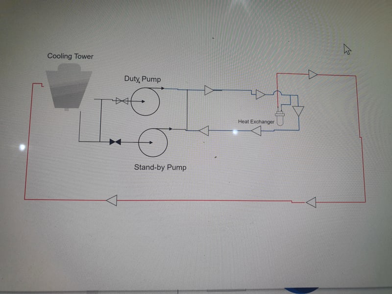
20211213_191400_ynplgr.jpg
 
Thank you for the response. Here is the simplified system. There system had multiple heat exchangers in reality
 
Thank you.

You do not have a simple system. Please make a more complete diagram. What machines? I see pumps, heat X and a cooling tower. I do not see diameters, or distances.

Why have two pipes supplying the HX? The bottom pipe will not return flow into the standby pump discharge. Flow in both ring pipes will be from the pumps to the HX direction. The return lines from the unknown machines will affect the flow to the machines.

 
Only one pipe is supplying the heat exhanger. The red, second line is returning the hot water back into the cooling tower
 
Zaheer said:
I'm having some trouble understanding the pressure and flow rates within each branch.
Show us the data/problem.

Zaheer said:
Further more, at the the last machine, the outlet pipe from the cooling tower (carrying cold water) RETURNS to the pump creating a ring.
Show us this detail on the drawing.

How many heat exchanger/mould pairs do you have? Can you detail the piping of one of them please? AND, the last one!

Good Luck,
Latexman
 
Thanks Latexman
Ok I will try and draw a detailed P & ID. I will add all the relevant data and resend the document.
 
See what I mean. 7 posts and still nowhere.
Now you will have to deal with the night shift.

 
Your description of flow is incorrect.

When one pump is running the flow will split at that first node and travel around the loop in both directions until the flow reaches a neutral point doing on where the take off flow is. So the two arrows in your lower leg in the diagram are the wrong way around. The pressure at a junction must be the same in both legs at the node point.

This is like a ring main with a single entry point. Depending on the flow, length and size of ring main and size of pump, the pressure MAY be similar at each location.

This will help even to the flow through the connections.

But it might not be that simple.

Remember - More details = better answers
Also: If you get a response it's polite to respond to it.
 
Thank you for the response. I do understand that at the node, the flow splits. I tried as best as I could to provide a detailed drawing.
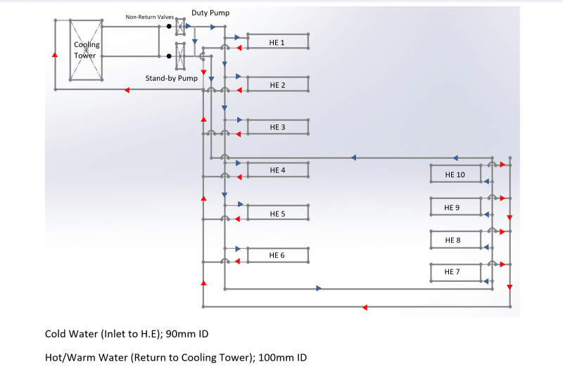
Screenshot_2021-12-14_093804_lg1x9y.png
 
You do not show distances for the length of each pipe.
Do all heat exchangers operate at the same time?

Your cold water arrow near HX10 to HX4 is going in the wrong direction.
Ring_Main_llmnov.png


Rughly half of the total flow goes through pump to HX1, the other half goes through pump to HX10, that is if pump to HX1 distance is equal to pump to HX10 and if all HX are working at the same time.

It is a little strange that you seem to need two 90mm pipes to supply tghe cold water, but only 1, 100mm pipe to take it away. Your supply divides the total supply flow by 2, so half the total in each supply pipe. Your return line puts all the flow in one line, but both lines are close to the same diameter. Why, when the supply pipes have half the flow of the return line? You should reverse the supply and return lines.

More hydraulically logical configurations would be,
If you keep that configuation, I would make the 2 supply lines 90mm and the one return line 125mm.
You could also make the return lines a ring with all pipes 90mm.
Or you could have 2 x 90mm return lines and 1 x 125mm supply line.

Having twice the flow in the 100mm return pipe that you have in the two 90mm supply pipes = does not appear entirely logical, but maybe you need a greater pressure drop in the return line than you have in the supply line.
 
thank you Petroleum for the response. In theory, shouldn't there be a neutral point where the convergence of flow occurs? or it does not work like that?
 
Quite an interesting system alright.

What you have here though is a header and branch system. They work in two ways.

Either the header pipe is large compared to the outlet pipes and pressure drop along the header from one end to the other or the mid point in this example is low compared to the pressure drop across the branches OR

the header pipe is small compared to the outflow pipes and pressure drop is significant from one end to the other or the mid point in a ring system.

So your 90mm header essentially should be feeding 5 of your units. what is the size of the offtakes? what is the flow?

what are the pressures at the pump and the start of the return line?

you can work this out "manually" by taking each section as an individual pipe between nodes, but there are many network models which will do it for you.

Do you have flow control on the HX's?

Are you just curious or is there a know issue of one unit not getting enough flow?

And yes, there is a point where the fluid flow in you ring will be stationary, but it is after the first offtake (HE10)

Remember - More details = better answers
Also: If you get a response it's polite to respond to it.
 
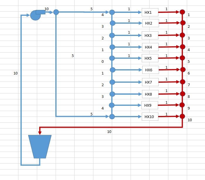
The ideal is,
If all HX have the same flow, the 0 flow point is between HX units 5 and 6.
Each unit represents the flow in each HX.
Ring_Main_qqo03h.png


Since the return line is not symetrical, HX1 has a much greater exit pressure than HX10 exit pressure and the inlet pressures of HX1 and HX10 are initially equal, flows in each HX will not be equal. Inlet pressures will want to be the same, but outlet pressures will not permit that, thus a new equilibrium point may result which actually tends to change all the individual HX flows. I the return line has 2 x the area of the 2 supply pipes combined, the HX flows would try to equalize again. If the return line was connected at HX5/HX6 to the cooling tower, that would also help equalize the flows in each HX.

You should be trying to make the most symetrical pipe cofiguration that you can. Removing one supply pipe, pump to HX10, could also help, if the supply pipe diameter was the same as the return pipe diameter. That would also be a "hydraulicly symetrical" configuration because the supply pipes are exactly the mirror of the return pipes.
 
Only if the distance between each is the same....

We have no distances or flows so the neutral point could be anywhere between HE1 and HE10...

Remember - More details = better answers
Also: If you get a response it's polite to respond to it.
 
Right. I asked for the lengths, but they were not given, so i'm just working with the most likely assumptions consistent with the very sparse nature of the info he has given. Given limited info, he will just have to be content with the approximate results.

And I don't really want to solve this problem, just point the way. At least he's got the arrows going the right way now and, if he's not happy with the appx results, he can ask another question.
 

Thank you very much for the responses. Really appreciate it. I will add the lengths and resend the document. Thanks again.
 
Also flows and pressure drops if you know them

Remember - More details = better answers
Also: If you get a response it's polite to respond to it.
 
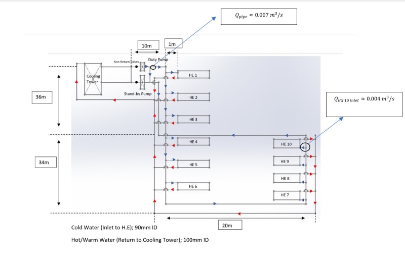
dfsfs_pxolwb.jpg


i have attached the distances. Distance from the heat HX outlet to the main return line is also 1m. Furthermore, i stipulated the flows along the route that i could determine.

To answer the questions:
1. there are no gauges so i cannot determine the pump pressures at the start and end of the lines.
2. Each HX has a ball valve to control the flow.
3. The HX are different sizes.
4. Reason of doing this study is to determine if i add on more machinery;
a. will it affect the flow through the current lines of machines.
b. will the current pump be adequately rated for an additional head loss due to an increase in pipe length, loss due to bends, taps etc.
5. The offtakes are 1'' each for both the inlet to HX and outlet of HX back into the main return line.
 
Status
Not open for further replies.

Part and Inventory Search

Sponsor