Continue to Site

Eng-Tips is the largest engineering community on the Internet

Intelligent Work Forums for Engineering Professionals

  • Congratulations pierreick on being selected by the Eng-Tips community for having the most helpful posts in the forums last week. Way to Go!

RISA-3D Plate Principal Stresses

Status
Not open for further replies.

SteelCrane

Structural
Oct 16, 2024
5
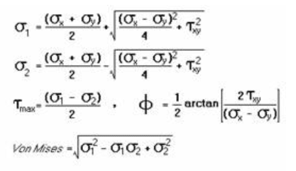
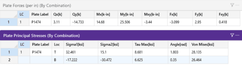
Can someone explain how RISA-3D calculates Plate Principal Stresses? Specifically, how does it derive σx, σy, and τxy for use in the Mohr's Circle calculations that lead to σ1, σ2, τmax, and σVon-Mises? The methodology is described here. The Plate Forces and Plate Principal Stresses for a 2.25" thick plate output by RISA-3D are:

results_hfaijv.png


Here's what I've tried:

fax = Fx / tpl = -1.377 ksi
fay = Fy / tpl = 1.311 ksi
fbx = 6*Mx / tpl2 = 17.399 ksi (+ at top)
fby = 6*My / tpl2 = 30.229 ksi (+ at top)
fbxy (warp) = 6*Mxy / tpl2 = -4.077 ksi
fxy = Fxy / tpl = 0.186 ksi
fxz = Qx / tpl = 1.382 ksi
fyz = Qy / tpl = 6.548 ksi

Attempt #1:
σx = fax + fbx + fbxy (warp)
σy = fay + fby + fbxy (warp)
τxy = max of:
{fxy and fxz resolved}​
{fxy and fyz resolved}​

Resulting error: 17% for σ1, 17% for σ2, 17% for τmax

Attempt #2:
σx = fax + fbx
σy = fay + fby
τxy = max of:
{fxy and fxz resolved}​
{fxy and fyz resolved}​

Resulting error: 5% for σ1, -10% for σ2, 17% for τmax

Attempt #3:
σx = fax + fbx
σy = fay + fby
τxy = fxy

Resulting error: -3% for σ1, 6% for σ2, -11% for τmax

Attempt #4: at this point, I gave up and backsolved the RISA-3D Principal Stress results to find σx, σy, and τxy, and it led to this:
σx = fax + fbx (excluding warping) = 16.02 ksi
σy = fay + fby (excluding warping) = 31.54 ksi
τxy = 3.89 ksi; a number I can't derive using any combination of Fxy, Qx, and/or Qy

Resulting error: 0% for σ1, 0% for σ2, 0% for τmax

Given that fxy = 0.186 ksi, fxz = 1.382 ksi, and fyz = 6.548 ksi, how did it come up with 3.888 ksi? And why would the warping moment be excluded?

Thanks for your help!
 
Replies continue below

Recommended for you

Generally, the conversion from moment to stress is:

Sigma = M*c/I

For a rectangular beam this would be:

Sigma = M * t/2 / (b*t3/12) = M/S = M*6/[b*(t^2)]

It's basically the same with plate flexural stresses. But, plate moment are already based on a per width (b) basis.

Sigma_x = Mx * 6 / (t^2)

Do the same calculation for My and Mxy....Right?
 
JoshPlumSE,

Correct, I did that for the moments (copying from above):

fbx = 6*Mx / tpl2 = 17.399 ksi (+ at top)
fby = 6*My / tpl2 = 30.229 ksi (+ at top)
fbxy (warp) = 6*Mxy / tpl2 = -4.077 ksi

But shouldn't σx and σy, for use in the equations below, also include axial stress and warping moment stress?

r3d_gkp7uz.png


What I'm trying to understand is how RISA-3D arrived at the Principal Stresses (shown above) using the Plate Forces (shown above). It appears that RISA-3D left the warping moment out of its calculation of σx and σy, and I have no idea how it got the shear value of 3.888 ksi.
 
Sorry, I wasn't understanding your full post. Plus, I haven't had to think about this in ages.

Yes, I believe the flexural stresses (fxy) due to the distortional moment (Mxy) are NOT Sigma 1 and Sigma 2 calculations. But, I don't think they act on the same faces and in the same directions as the regular flexural stresses.

I believe they SHOULD include the Axial stresses as well.

I don't think Qx and Qy should contribute to the Sigma 1 or Sigma 2 values at all.

I believe the Txy value should be based on a combination of Fxy and Mxy.

 
"I believe the Txy value should be based on a combination of Fxy and Mxy." Bingo, thanks! So the warping moment Mxy gets added to Mx and My for concrete reinforcement design, but it gets added to τxy for finding Principal Stresses in steel. That's odd.

The equations below caused my results to match RISA-3D output:

σx (top) = fax + fbx
σy (top) = fay + fby
τxy (top) = fxy + fbxy (warp)

σx (btm) = fax - fbx
σy (btm) = fay - fby
τxy (btm) = fxy - fbxy (warp)
 
I'm glad you figured it out!! Just curious, is there a reason why you didn't ask RISA tech support for an explanation? I've heard some rumor that there tech support wasn't very good any more and I have to ask.

Note, the two situations are really pretty different. With principal we're usually looking at yield criteria or buckling criteria and (I believe) there are lots of established rules for .

For reinforcement design, usually design is based on the Wood-Armer method. Which is different. It's less structural mechanics and more "practical" fudge factor than will make it easier to convert FEM forces and moments into a conservative design.

Personally, I tend to use the "plate corner force" output as the basis for reinforcement design. It just feels like a more "direct" way to get your design forces and moments.
 
Ooops, I forgot to include my legal caveat (so that I don't get sued).

I worked for the original version of RISA for 16 years. I was their Vice President of Support / Training / Engineering or some BS fancy title along those lines. I left when that company ceased to exist and the rights to that software were sold to Nemunchenk (or however you spell it). There were some hard feelings when I left, so I am not an unbiased observer and take anything I say about them with that in mind.

FWIW, it's been something like 7 years.... and I think any hard feelings that used to exist on my end are gone. I should probably keep posting this caveat because they have threatened to sue me for talking about this new company before. LOL. I've never said anything that I didn't believe was true. But, they don't like that their former technical spokesperson could reveal information that might make them look bad. Personally, I think they should have been concerned more about "mismanagement" or what appears to be a tendency to hold their customers in disdain that they should be more concerned about.
 
looking bad is worse than being bad ?

"Wir hoffen, dass dieses Mal alles gut gehen wird!"
General Paulus, Nov 1942, outside Stalingrad after the launch of Operation Uranus.
 
I also emailed RISA tech support earlier, but I expected I'd get a quicker answer here.

Good to know about (Mx + Mxy) being an approximation, not directly a mechanical behavior. Is Mxy more like rolling shear in plywood? It seems like Fxy shears would shear along the yz-plane but Mxy shears would shear along the xy-plane, making their direct addition an approximation just like (Mx + Mxy) is an approximation.
 
The reply from RISA just came in, and they confirmed what we've talked about here.
 
There are two papers that I like to point people towards for Twisting Moments in slabs:

Twisting Moments in Two-Way Slabs: Design Methods for torsion is slabs using finite element analysis by Myoungsu Shin, Allan Bommer, James Deaton, & Bulent Alemdar. Which was published in Concrete International in 2009.

"Reinforced Plate Design for Mxy Twisting Moment" by John Li.... But, I couldn't find a good link for this one.

There is also ACI 447R-18: Design Guide for Twisting Moments in Slabs, but I don't have a copy of this one. Though, maybe I should purchase it.
 
Status
Not open for further replies.

Part and Inventory Search

Sponsor