Vish S
Mechanical
- Mar 21, 2024
- 14
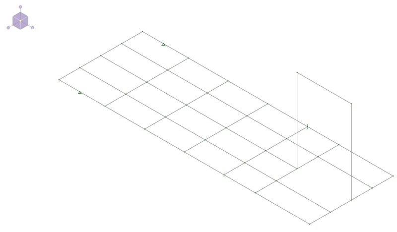
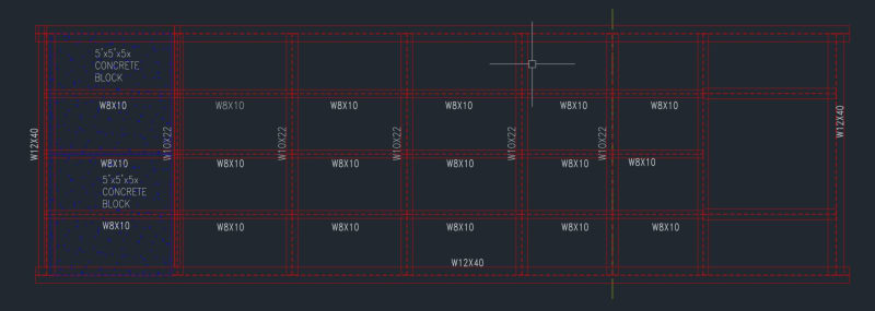
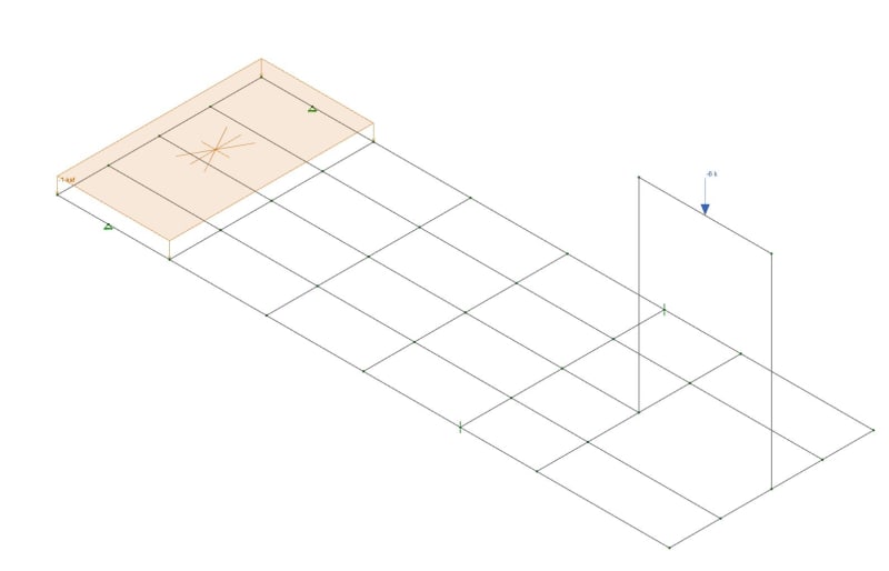
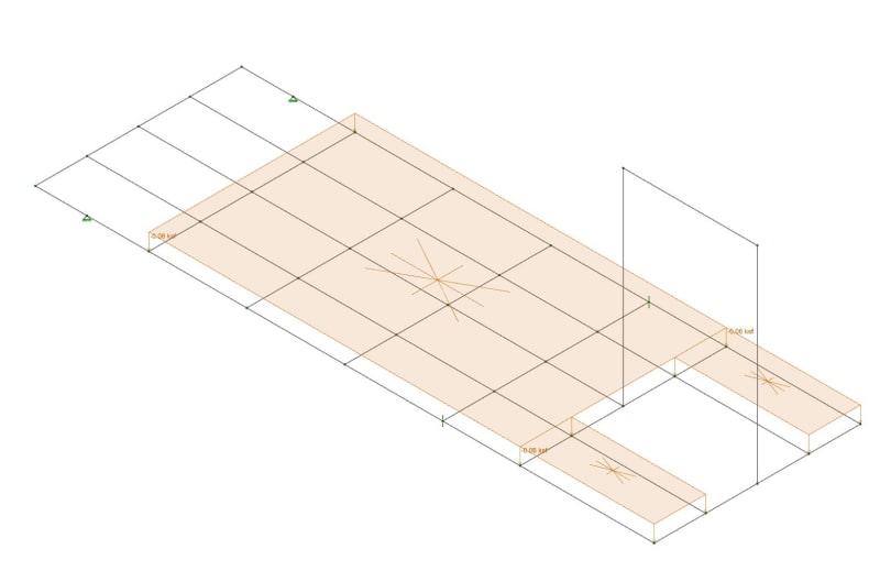
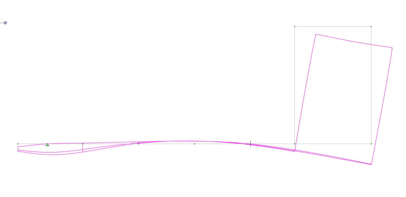
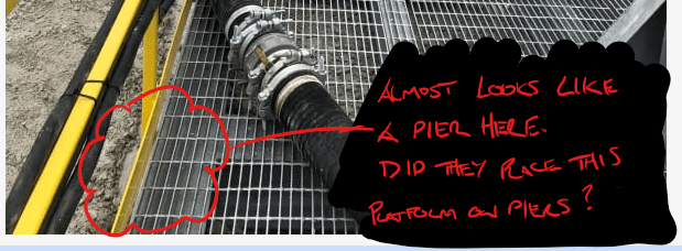
I am new to RISA and taking over a project from a guy who left the company. This project has a platform with grating all around except at one end (See image2). Currently, in the opening on right side of ACAD image, there's a crane suspended pump and to counter it on left side there's 2 5 ton blocks. Now, the pump is being replaced by vertical turbine pump which approx. weighs 2500lbs more than previous one. So I am trying to figure out how much more counter weight I am supposed to put so that the platform isn't tipped over. If you look in image2, the platform is on ground till the yellow phantom line and is suspended in air yellow phantom line onwards. The RISA file the previous guy built I am not sure is quite right or what more modifications are required to make the project feasible. I ran the model with existing conditions. I have the attached them as well. I have below questions:
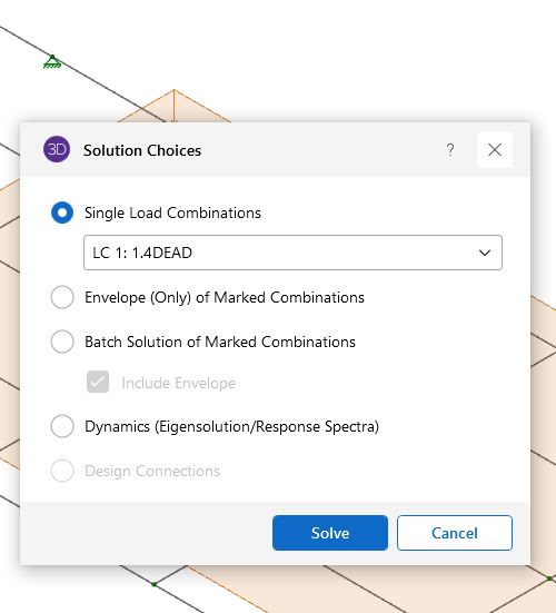
1) What option should I use when I solve the model?
2) Practically, when the pump is installed the platform should be straight, in RISA when we have the results should show minimal or no deflection on the side with pump right?
3) I ran the models by increasing the counter weights on the left but the result is same so need some more modifications but not sure what am I supposed to do.
Any help on this appreciated, any more information needed do let me know.
- Vishwa

